
Operating Instructions
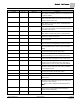
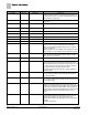
Table Of Contents

Chapter 3 – Point Database
16
Siemens Industry, Inc. Owner's Manual 125-5070
2015-05-07
Descriptor
Address
1
Application
Description
velocity sensor is located. This value is calculated by the
portable operator’s terminal or by the field panel depending
on duct shape and size. It is used in calculating all points in
units of CFM, CF, LPS, and L.
HTG P GAIN 67 2032, 2033 The proportional gain value for the heating temperature
control loop.
HTG I GAIN 68 2032, 2033 The integral gain value for the heating temperature control
loop.
HTG D GAIN 69 2032, 2033 The derivative gain value for the heating temperature control
loop.
HTG BIAS 70 2032, 2033 The biasing of the heating temperature control loop.
FLOW P GAIN 71 All
except
2092 The proportional gain value for the cooling flow control loop.
FLOW I GAIN 72 All
except
2092 The integral gain value for the cooling flow control loop.
FLOW D GAIN 73 All
except
2092 The derivative gain value for the cooling flow control loop.
FLOW BIAS 74 All
except
2092 The flow loop bias value.
FLOW {75} All
except
2092 Indicates the actual amount of air currently passing the air
velocity sensor. The value is calculated as a percentage
based on where AIR VOLUME is between CTL FLOW MIN
and CTL FLOW MAX.
If AIR VOLUME = CTL FLOW MIN, then FLOW will be 0%.If
AIR VOLUME = CTL FLOW MAX, then FLOW will be 100%.
CTL TEMP 78 All
except
2092 The temperature used as input for the temperature control
loops. This value will be the same as the value in ROOM
TEMP, unless it is overridden.
HTG LOOPOUT 80 2032, 2033 The heating temperature control loop output value in percent.
AVG HEAT OUT {81} 2032 This point is used to determine what stages of electric heat
are used for a given loop output value. The ranges for the
value are determined by the number of stages used: 0 to 100
for 1 stage of electric heat, 0 to 200 for 2 stages of electric
heat, and 0 to 300 for 3 stages of electric heat.
With electric heat, this value is equal to: HTG LOOPOUT ×
STAGE COUNT.
STAGE MAX 82 2032 The value in percent that the heating loop (HTG LOOPOUT)
must exceed for the electric heat to be ON for the full duty
cycle (STAGE TIME).
STAGE MIN 83 2032 The value in percent that the heating loop (HTG LOOPOUT)
must go below for the electric heat to be OFF for the full duty
cycle (STAGE TIME).
DMPR STATUS {84} All
except
2092 This point is used only when CAL MODULE is set to YES. It
readjusts the damper position if the command value is not
equal to the actual position of the damper. CAL indicates that
the damper is operating normally. RECAL indicates that the
damper position was adjusted (recalibrated) by 25% because
the desired airflow was not obtainable under its current
status.
CAL MODULE 87 All
Indicates the presence of Autozero Modules at DO 7 and DO
8. YES indicates that Autozero Modules are to be used to
calibrate the controller’s air velocity transducers. NO
indicates that calibration will take place without the Autozero
Modules.
Valid input: YES or NO.