
Operating Instructions

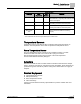
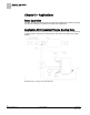
Table Of Contents

Chapter 1 – Product Overview
Power Wiring
8
Siemens Industry, Inc. Owner's Manual 125-5070
2015-05-07
Power Wiring
The controller is powered by 24 Vac. Power wiring connects to the three screw
terminals on the controller board labeled “C” (Common), “H” (Hot), and “E” (Earth
Ground) on the terminal block labeled “24 Vac”.
Communication Wiring
The controller connects to the field panel by means of a Floor Level Network (FLN)
trunk. Communication wiring connects to the three screw terminals on the controller
labeled “+” (positive), “-“ (negative), and “
” (reference).
Controller LED Indicators
NOTE:
The TX and RX LEDs indicate communication over the FLN.
To determine if the controller is powered up and working, verify that the Basic Sanity
Test (BST) Light Emitting Diode (LED) is flashing ON/OFF once per second. The
controller has nine Light Emitting Diode (LED ) indicators (see Figure Siemens BACnet
VAV Controller).