
Installation Instructions

Rev. 3, 5/91 Installation Instruction 540-197
Copyright
1991 by Landis & Gyr Powers, Inc.
Printed in U.S.A. Page 1 of 2
INSTALLATION INSTRUCTIONS
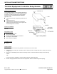
Terminal Equipment Controller Relay Module
PRODUCT DESCRIPTION
The Terminal Equipment Controller Relay Module has
four high voltage (240 Vac, 1.2 Amp maximum) relays
mounted on a printed circuit board. A relay module
must be used in a Terminal Equipment Controller
application if the:
controlled load is high voltage AC (greater than 24
Vac).
controlled load is DC.
controlled load is powered from a transformer
separate from the transformer used to power the
Terminal Equipment Controller.
PRODUCT NUMBER
540-147
REQUIRED TOOLS
Medium-duty electric drill
1/8-in. (3 mm) drill bit
Medium and small flat-blade screwdrivers
Center punch and hammer
Wire cutters and strippers
PREREQUISITES
None
Figure 1. Relay Module.
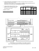
INSTRUCTIONS
1. Remove the cover from the relay module. Do not remove the cover screws.
2. Using the bottom housing as a template, mark the outermost four mounting holes with a center punch. (Refer
to Figure 1.)
3. Drive the four self-drilling screws into the mounting surface to fasten the bottom housing to the mounting
surface.
-OR-
If you do not wish to self-drill the screws, drill four 1/8-inch (3 mm) pilot holes.
4. Remove the appropriate knockout from the relay module. Route the wires through the opening.