
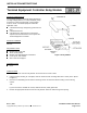
Installation Instructions

Installation Instruction 540-197
Page 2 of 2 Rev. 3, 5/91
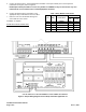
5. Connect the wires from the Terminal Equipment Controller to the input terminal pins on the relay board
(numbered 1 through 5). Refer to Figure 2.
NOTE:Input terminal pin number 1 on the relay module is COMMON. It may be connected to any even
numbered DO screw terminal on the Terminal Equipment Controller.
6. Connect the wires from the load device to the
appropriate relay terminal block. Refer to Table 1.
7. Place the cover over the bottom housing and
secure with the cover screws.
Installation is complete.
EXPECTED INSTALLATION TIME
18 Minutes
Table 1. Relay Module Connections.
Input
Controller*
Pin
Relay Terminal Block
DO
Screw
Terminal
1 -- COMMON DO3 6
2 K1 COM1, NO1, NC1 DO3 5
3 K2 COM2, NO2, NC2 DO4 7
4 K3 COM3, NO3, NC3 DO5 9
5 K4 COM4, NO4, NC4 DO6 11
* Sample for Heat Pump Application 70. Refer to Figure 2.
Figure 2. Sample Wiring Diagram for Heat Pump Controller Application 70.