
Installation Instructions


Document No. A6V10549963
Installation Instructions
January 13, 2016
Page 2 of 7 Siemens Industry, Inc.
Product and Part Numbers
Product
Description
DXR
Actuator
DXR2.M12P/102B/GDE
DXR2.M12P*
GDE131.1U*
*
To replace a component, order the individual component
part number, not the “product” number.
Accessories
Product
Description
550-002
Large Equipment Controller Enclosure
DXA.H180
Terminal cover for DXR.. 180 mm, 2
pieces
985-124
499 OHM RESISTOR ASSEMBLY KIT
SP386A
USB Isolator
Expected Installation Time
18 minutes
Required Tools
● 1/4-inch hex nut driver
● Electric drill and 1/8-inch (3 mm) drill bit (or other
bit size) if self-tapping screws are not used
● Small, flat-blade screwdriver
● 4-mm hex wrench (supplied)
● Torque wrench
● Pencil
● Pliers
● Ruler (or something to measure diameter of
damper shaft)
● Wire cutters
Prerequisites
All wiring must conform to NEC and local
codes and regulations.
The mounting screws provided are designed
for common sheet metal duct surfaces.
Have appropriate mounting hardware on
hand if another surface is used.
NOTE:
If the controller is being installed on a box
with 1 or more stages of electric heat, the
550-809 MOV with pre-terminated spade
connectors must be installed across the
manufacturer-supplied airflow switch.
MOVs can be installed at the time the
controller is factory-mounted; coordinate
with the box manufacturer prior to order
placement. For field installation, see
Metal Oxide Varistor Kit Installation
Instructions (540-986).
CAUTION
Protect the DXR Actuator Package
from metal shavings when drilling
holes in the enclosure or mounting
surface. Metal shavings can
severely damage the controller.
Instructions
For actuator replacement, see
Actuator
Replacement
section.
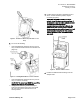
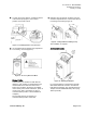
CAUTION
DO NOT cut the cable tie (Figure 1)
that secures the actuator until Step
7.
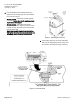
1. Determine the damper shaft diameter. Do one of
the following:
– If it measures 1/2-inch (12 to 14 mm), skip to
Step 3.
– If it is not 1/2-inch (12 to 14 mm), remove the
black plastic guide piece from the hub of the
actuator (Figure 2).
NOTE: If necessary, you may destroy the guide
piece in order to remove it.