
Installation Instructions


Document No. A6V10549963
Installation Instructions
January 13, 2016
Siemens Industry, Inc. Page 3 of 7
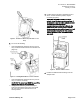
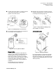
Figure 2. Guide Piece Removal (Shaft Size not 1/2-
Inch).
2. Do one of the following:
– If the shaft diameter measures 3/8-inch (8 to10
mm), install the metal insert into the actuator hub
(Figure 3).
Figure 3. Installing Metal INsert for 3/8-inch Shafts.
– If the shaft diameter measures 5/8-inch (15 to17
mm), no insert is necessary.
CAUTION! The metal insert MUST be used if the
damper shaft diameter equals 3/8-inch.
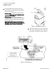
Using pliers if necessary, rotate the damper
shaft counterclockwise until it fully stops. Mark
the end of the shaft for reference if it is not
already marked.
3. Confirm that the actuator’s adjustment lever is
also in counterclockwise position; adjust if
necessary (Figure 4).
CAUTION! The DXR circuit board and the
actuator have little clearance between them. If
the actuator is secured with its adjustment lever
in clockwise position (instead of
counterclockwise as called for in Step 4), the
slight side-to-side movement of the actuator
during normal operation will be toward the circuit
board instead of away from it. If the actuator
impacts the circuit board, equipment damage
may result.
Figure 4. Actuator Initial Position.
4. Position the DXR Actuator Package onto the
damper shaft.