
Installation Instructions


Document No. A6V10549963
Installation Instructions
January 13, 2016
Siemens Industry, Inc. Page 5 of 7
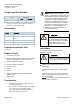
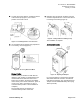
7. Cut and remove the cable tie, confirming release
of the location pin (Figure 7) to its neutral
position. Push it free if stuck.
Figure 7. Confirming Release of Location Pin.
8. If a mechanical range (damper stop) adjustment
is necessary, do it now (Figure 8).
Figure 8. Accessory Kit Holes ONLY.
Damper Position
In most cases, you will want to finish with the
damper in open position so that airflow through
ductwork will not be obstructed. Since most
boxes open clockwise, the damper is probably
closed at this point in these instructions. (If this is
not the case—that is, the damper is open in
counterclockwise position—then installation is
complete.)
Proceed with Step 9 if the damper is in
counterclockwise position and closed.
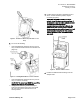
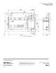
9. Manually open the damper clockwise using the
actuator’s adjustment lever. Use the hex wrench
for leverage if necessary (Figure 9).
Figure 9. Setting a Mechanical Range Stop.
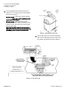
The installation is complete.
Additional Information
Figure 10. Opening the Damper.
For more information on the Siemens OpenAir
GDE Series Electronic Actuator used with the
DXR Actuator Package, see
OpenAir Electronic
Damper Actuator GDE/GLB Rotary Non-spring
Return
(129-367).