
Installation Instructions

Installation Instructions
Document No. 540-201
August 31, 2007
TEC Plug-in Relay Module
Siemens Building Technologies, Inc. Page 1 of 6
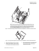
Product Description
The TEC Plug-in Relay Module (called relay module
in these instructions) plugs directly (or remotely with
a Remote Mount Kit) into the Terminal Equipment
Controller (TEC) to provide relay isolation for at least
four digital outputs (DOs). (Part Number 550-048
provides isolation for up to six DOs. See Table 1.)
Per NEC and local codes, voltages up to 230 Vac
and 4 amps can be switched. For remote
installations, a TEC Plug-in Relay Module Remote
Mount Kit is required in addition to the relay module.
See Table 1.
A relay module must be used if the:
• TEC’s digital output (DO) is required by a
specific manufacturer to be inverted and
used to drive electric heating coils. (Specific
wiring requirements can differ depending on
the manufacturer; consult with the local
Siemens Building Technologies
representative if in doubt.)
• Controlled load is greater than 12 VA.
• Controlled load is greater than 24 Vac.
• Controlled load is DC.
• Controlled load is powered from a
transformer that is separate from the
transformer used to power the TEC.
• Controlled load is suspected of creating
electromagnetic interference or noise in the
control signal.
Shipping carton includes a printed circuit assembly
in a static proof bag, a ground wire, and a high-
voltage warning sticker. The Remote Mount Kit
includes a mounting rail, self-tapping screws, and a
cable assembly.
NOTE: The Remote Mount Kit does not come
with a grounding wire. For remote
installations, the ground wire that comes
with the relay module must be used.
Product Numbers
Table 1. Relay Module and Controller Combinations.
Plug-in Relay
Module
Remote
Mount Kit
Controller Switched DOs
TEC 540–xxx*
Numbers
Example
550-054 550-058
Short Platform — 16-
position terminal block
3, 4, 5, 6
Refer to
Figure 4
550-054 550-058
Short Platform — 16-
position terminal block, as
part of the TEC Actuator
Package
3, 4, 5, 6
100(C/K), 103(C/K),
104(C/K), 105, 106,
107, 110(C/K),
200(C/K), 800, 803,
804, 808, 809
Refer to
Figure 6
550-050 550-056
Long Platform — 20-position
terminal block
5, 6, 7, 8 506, 507
Refer to
Figure 5
550-048 550-057
Long Platform — 24-position
terminal block
3, 4, 5, 6, 7, 8 505
Refer to
Figure 5
* C = Secure Mode TECs; K = UL Smoke Control Listed TECs.