
Installation Instructions

Document No. 540-201
Installation Instructions
Rev. BA, August 2007
Installation Conventions
CAUTION
Equipment damage or loss of
data may occur if the user
does not follow procedure as
specified.
Page 2 of 6 Siemens Building Technologies
WARNING
Personal injury or loss of life
may occur if a procedure is not
performed as specified.
Required Tools
• Small flat-blade screwdriver
• 1/4-inch (6.35 mm) hex nut driver
• Electric drill and 1/8-inch (3 mm) drill bit (or
other bit size) if supplied screws are not
used (remote installations only)
Prerequisites
WARNING:
TEC enclosure must be at earth
ground potential.
CAUTION:
For electric reheat or heat pump
applications, or where noise
suppression is an issue, consult with
the local Siemens Building
Technologies representative to
determine the specific manufacturer’s
wiring requirements.
• TEC enclosure must be at least 4 3/4-inches
deep to accommodate the relay module.
Compatible Siemens enclosures are
550-002 and 540-154. 540-154 may be
seen on job sites installed previously but it is
no longer orderable. (Remote installations
may not require the enclosure to be 4 3/4-
inches deep. See Remote Installation
section.)
• Power to TEC and all switched devices is
OFF.
NOTE: All points can be wired to the TEC
terminal block per instructions supplied
with the controller except those
controlled by DOs that will be switched
by interposing relays on the relay
module. (Refer to Table 1 to determine
which DOs are switched.) If points to
be switched are already wired to the
terminal block, they may need to be
individually labeled and disconnected.
See Figure 1 for more information.
Expected Installation Time
2 Minutes Direct Installation
6 Minutes Remote Installation
Direct Installation
Direct installations only. See Remote Installation
section for remote installations.
NOTES:
1.
a
Placement of the TEC Plug-in Relay Module
and all wiring must conform to NEC and local
codes and regulations.
2.
b
High-voltage applications (120 to 230 Vac)
may require external snubbers (filters) to
eliminate electromagnetic interference and/or
conform to FCC regulations.
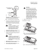
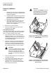
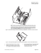
1. Remove cover of TEC enclosure.
2. Confirm that power to the controller and all
switched devices is OFF.
3. Unplug and wire up the terminal block, wiring
switched DOs per the example in Figure 1.
(See Table 1 to determine which DOs are
switched.) Wire unswitched DOs normally.
NOTE: Any point whose controlling DO is
switched by the TEC Plug-in Relay
Module must be wired as in Figure 1,
even if it would not normally
require a relay.