
Installation Instructions

Document No. 540-201
Installation Instructions
Rev. AA, August 2007
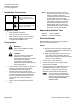
NO
DIGITAL OUTPUT
FROM TEC
CONTACT CAN HANDLE
UP TO 230 Vac
AT 4A
BY OTHERS
TEC0288R1
LOAD
SELECT SOURCE VOLTAGE
(HOT OR NEUTRAL)
AS REQUIRED
C
RELAY
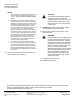
IMPORTANT: Any point whose controlling DO is switched
by the TEC Plug-in Relay Module must be wired as
shown, even if it would not normally require a relay.
Figure 1. Wiring Requirements for Switched DOs.
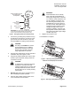
4. Connect the grounding wire provided to the lug
at terminal J3 (see Figure 2). Ground J3 to the
ground stud in the TEC enclosure. (The TEC
enclosure must be at earth ground potential.)
CAUTION:
The relay module MUST be at earth
ground potential. If not, the MOVs
(metal oxide varistors) on the relay
module cannot provide noise and
surge suppression for the TEC.
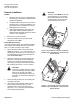
5. Plug the relay module firmly into the controller’s
termination strip. See Figures 2 and 3.
6. Plug the fully wired terminal block into the relay
module’s open receptacle, making certain the
connection is secure.
CAUTION:
To minimize the potential for electrical
interference, route any wires with
voltages greater than 24 Vac away from
the relay module and the TEC. Do not
let them pass over or in close proximity
to these units.
7. DO NOT apply power to the controller without
first consulting the system specialist.
8. Place the high-voltage warning sticker on the
cover of the TEC or the enclosure.
WARNING:
Field technicians do not normally
think of the TEC terminal block as
having high-voltage wires connected
to it. However, these instructions call
out the possibility of voltages up to
230 Vac being wired directly to the
terminal block once it is in place on
the relay module. While applications
requiring the relay module to switch
voltages this high may be rare, it
remains a possibility. Therefore, the
warning label must be placed to alert
future technicians that a high-voltage
condition may exist.
9. Replace the enclosure cover.
The installation is complete.
24 V-AC
CEH
DO 1 DO 2 DO 3 DO 4 DO 5
NO C NO C NO C NO C NO C
DO 6
DI 3 DI 2
LAN
TRUNK
NO C
AI 3
TX RX
+-S BST RTS
1 2 3 4 5 6 7 8 9 10 11 12 13 14 15 16
C H
+ - S
TEC0286R1
J3
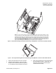
Figure 2. TEC Plug-in Relay Module and Short
Platform Terminal Equipment Controller.
CEH
DO 1 DO 2 DO 3 DO 4 DO 5
NO C NO C NO C NO C NO C
DO 6
DI 3 DI 2
LAN
TRUNK
NO C
AI 3
TX RX
+-S BST RTS
1 2 3 4 5 6 7 8 9 10 11 12 13 14 15 16
C H
+ - S
1 2 3 4 5 6 7 8 9 10 11 12 13 14 15 16
TEC0287R1
Figure 3. TEC Plug-in Relay Module Plugged-In.
Siemens Building Technologies Page 3 of 6