
Installation Instructions

Document No. 540-201
Installation Instructions
Rev. BA, August 2007
TEC0296R1
J3
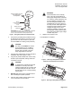
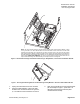
NOTE: The TEC Actuator Package is shipped with the actuator (and optional Autozero Module, if there
is one) pre-wired to the TEC’s terminal block. This terminal block must be removed so that the cable
assembly’s terminal block can be plugged into the TEC (as shown above). The wires from the actuator
(and optional Autozero Module) must be removed from the original TEC terminal block and inserted into
the cable assembly’s terminal block as illustrated. Also, the associated cable assembly wires (shown as
dashed lines) SHOULD BE REMOVED. This will ensure that disruptive signals cannot travel from the
relay module back through the cable assembly and corrupt the TEC’s control signals.
Figure 6. TEC Actuator Package and Remote Installed Plug-in Relay Module, in Enclosure Part Number 550-002.
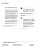
1
2
TEC0297R1
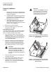
Figure 7. Securing the Mounting Rail for the Remote Plug-in Relay Module in Enclosure Part Number 550-002.
7. Unplug the terminal block from the controller.
8. Using the cable assembly, connect the relay
module to the controller as shown in Figures 4,
5, or 6. Make sure the connections are secure.
9. Wire up the terminal block, wiring switched DOs
per the example in Figure 1. (See Table 1 to
determine which DOs are switched.) Wire
unswitched DOs normally.
Siemens Building Technologies, Inc. Page 5 of 6