
Installation Instructions

Document No. 540-201
Installation Instructions
Rev. BA, August 2007
NOTES:
1.
Any point whose controlling DO is switched by the
TEC Plug-in Relay Module must be wired as in
Figure 1, even if it would not normally require
a relay.
2.
Depending on the code guidelines in effect and
the job specifications, you may want to physically
separate low voltage wiring from any high voltage
wiring attached to the terminal block. To do this,
wire the relay module terminal block only with
those wires that will carry voltages higher than 24
Vac. Wire all other low voltage point wiring
directly to the TEC by using the cable assembly’s
terminal block which is plugged into the TEC. As
you wire up these low voltage points, remove the
associated wires of the cable assembly that feed
into the relay module, thereby ensuring that
disruptive signals cannot travel from the relay
module back through the cable assembly and
corrupt the TEC’s control signals.
3.
If the TEC is part of a TEC Actuator Package,
then see important note accompanying Figure 6.
The actuator (and optional Autozero Module, if
there is one) should be wired directly to the TEC
using the cable assembly’s terminal block, and
the associated cable assembly wires should then
be removed.
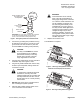
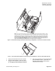
10. Plug the fully wired terminal block firmly into the
relay module’s open receptacle.
CAUTION:
To minimize the potential for electrical
interference, route any wires with
voltages greater than 24 Vac away from
the relay module and the TEC. Do not
let them pass over or in close proximity
to these units.
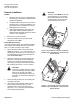
11. DO NOT apply power to the controller without
first consulting the system specialist.
12. Place the high-voltage warning sticker on the
cover of the TEC.
WARNING:
Field technicians do not normally think of
the TEC terminal block as having high-
voltage wires connected to it. However,
these instructions call out the possibility
of voltages up to 230 Vac being wired
directly to the terminal block once it is in
place on the relay module. While
applications requiring the relay module to
switch voltages this high may be rare, it
remains a possibility. Therefore, the
warning label must be placed to alert
future technicians that a high-voltage
condition may exist.
13. Replace the enclosure cover.
The installation is complete.
Information in this publication is based on current specifications. The company reserves the right to make
changes in specifications and models as design improvements are introduced.
© 2000 Siemens Building Technologies, Inc.
Siemens Building Technologies, Inc.
1000 Deerfield Parkway
Buffalo Grove, IL 60089-4513
USA
Your feedback is important to us. If you have
comments about this document, please
send them to
SBT_technical.editor.us.sbt@siemens.com.
Document No. 540-201
Printed in the U.S.A.
Page 6 of 6