Actuating Terminal Equipment Controller (ATEC) Base VAV - Cooling Only, Application 2520 Application Note 140-1217 2015-05-06 Building Technologies
Table of Contents Overview ............................................................................................................................. 4 Hardware Inputs .................................................................................................................. 5 Hardware Outputs ................................................................................................................ 5 Ordering Notes .............................................................................
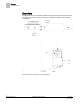
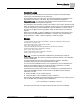
Overview Hardware Inputs Overview In Application 2520, the controller modulates the supply air damper of the terminal box for cooling. In order for it to work properly, the central air-handling unit must provide cool supply air. Application 2520 VAV Cooling Only Control Diagram. 4 Siemens Industry, Inc.
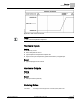
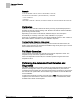
Overview Hardware Inputs Application 2520 Control Schedule. NOTE: 1. See Control Temperature Setpoints.
Sequence of Operation Control Temperature Setpoints Sequence of Operation The following paragraphs present the sequence of operation for Application 2520, Base VAV - Cooling Only. Control Temperature Setpoints This application has a number of different room temperature setpoints (NGT CLG STPT, RM STPT DIAL, and so on.). The application actually controls to CTL STPT. CTL STPT is set to different values depending on its override status, the time of day, and the type of RTS used.
Sequence of Operation Control Loops Control Loops The terminal box is controlled by two Proportional, Integral, and Derivative (PID) control loops; a temperature loop and a flow loop. The temperature loop is a cooling loop. The active temperature loop maintains room temperature at the value in CTL STPT. See Control Temperature Setpoints. Temperature Loop – A cooling loop that maintains room temperature at the value in CTL STPT. See Control Temperature Setpoints.
Sequence of Operation Calibration Example If CTL FLOW MIN = 250 cfm, and CTL FLOW MAX = 1000 cfm, the low limit of FLOW STPT = (250 cfm/1000 cfm) × 100% flow = 0.25 × 100% flow = 25% flow. Since 25% of 1000 cfm = 250 cfm, the minimum airflow out of the terminal box will be 250 cfm. Calibration Calibration of the controller’s internal air velocity sensor(s) is periodically required to maintain accurate air velocity readings. CAL SETUP is set with the desired calibration option during controller startup.
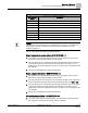
Sequence of Operation Performing the Automated Fault Detection and Diagnostics Possible Failure Value and Description CHK STATUS Values Description -1 Checkout procedure has not been run since last controller initialization. 0 No errors found. 1 RTS failed. 2 Room Setpoint dial failed (If STPT DIAL = YES). 4 AVS failed. 8 Controller could not reach CLG FLOW MIN or below. 16 Controller could not reach CLG FLOW MAX or above. 32 Controller did not read low (zero) flow when damper closed.
Sequence of Operation Performing the Automated Fault Detection and Diagnostics 2. The tubing connections for the air velocity sensor may be reversed. Re-pipe if HI and LO connections are incorrect. 3. The sensor or the VAV Actuator may be faulty. Controller could not reach CLG FLOW MIN or below—CHK STATUS = 8 1. The actuator may be loose on the shaft. Check that the set screw is fully tightened against the damper shaft.
Sequence of Operation Application Notes 2. The damper shaft may not be secured correctly to the actuator so that when the actuator is fully closed, the damper does not completely shut off airflow. 3. Airflow calibration (at zero) may need to be performed ensuring the damper is fully closed and/or the air handling unit is off. Application Notes If temperature swings in the room are excessive or there is trouble maintaining the setpoint, the cooling loop must be tuned.
Application 2520 Point Database Application 2520 Point Database Point Number Descriptor Factory Default (SI Units)2 Eng Units (SI Units) Slope (SI Units) Intercept (SI Units) On Text Off Text 1 CTLR ADDRESS 99 -- 1 0 -- -- 2 APPLICATION 2486 -- 1 0 -- -- {03} CHK STATUS -1 -- 1 -1 -- -- {04} ROOM TEMP 74.0 (23.44888) DEG F (DEG C) 0.25 (0.14) 48.0 (8.88888) -- -- 6 DAY CLG STPT 74.0 (23.44888) DEG F (DEG C) 0.25 (0.14) 48.0 (8.
Application 2520 Point Database Point Number Descriptor Factory Default (SI Units)2 Eng Units (SI Units) Slope (SI Units) Intercept (SI Units) On Text Off Text 64 CLG I GAIN 0.01 (0.018) -- 0.001 (0.0018) 0 -- -- 65 CLG D GAIN 0 (0.0) -- 2 (3.6) 0 -- -- 66 CLG BIAS 0 PCT 0.4 0 -- -- 71 FLOW P GAIN 0 -- 0.05 0 -- -- 72 FLOW I GAIN 0.01 -- 0.001 0 -- -- 73 FLOW D GAIN 0 -- 2 0 -- -- 74 FLOW BIAS 50 PCT 0.4 0 -- -- {75} FLOW 0 PCT 0.