
Installation Instructions

Document Number 550-308
Installation Instructions
Rev. 1, July, 2001
Page 2 of 9 Siemens Building Technologies, Inc.
24 V-AC
RX TX
RTS
FLN TRUNK
+ - S
BST
DO1
NO C
DO2
NO C
DO3
NO C
DO4
NO C
DO5
NO C
DO6
NO C
DI3
AI3
DI2
DO7
NO C
DO8
NO C
1 2 3 4 5 6 7 8 9 10 11 12 13 14 15 16 17 18 19 20
C H GND
TEC0321R1
CONTROLLER
BOARD
MOUNTING
HOLE
(2)
MOUNTING
RAIL
POWER
TRUNK
TERMINATIONS
INPUT / OUTPUT TERMINATIONS
DO LEDS
BST LED
RECEIVE LED
FLN
TRUNK
TERMINATIONS
ROOM TEMPERATURE
SENSOR / MMI PORT
TRANSMIT LED
COVER
1 2 3 4 5 6 7 8 9 10 11 12 13 14 15 16 17 18 19 20
+
-
S
C
H
E
AIR VELOCITY
SENSOR PORTS
HI
LO
LO
HI
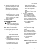
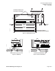
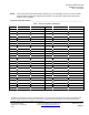
Figure 1. CE Compliant Dual Duct Controller — Two Air Velocity Sensors without Autozero Modules.
New Installation Instructions
1. Using the mounting rail as a template (Figure
1), mark the screw holes where you will install
the controller assembly.
2. Do one of the following:
• If using the self-tapping screws provided:
Using the drill and the hex nut bit, fasten the
mounting rail.
• If not using the self-tapping screws: Drill
two 1/8-inch (3 mm) pilot holes, then fasten
the mounting rail with No. 6 or No. 8 screws.
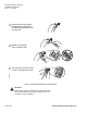
3. Place the ESD wrist strap on your wrist and
attach it to a good earth ground.
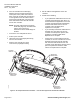
4. Carefully remove the controller assembly from
the anti-static bag. Center it over the mounting
rail and snap it securely into place.
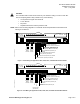
5. Connect the Floor Level Network (FLN). See
Figure 4.
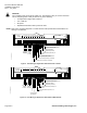
6. Connect the point wiring as shown in Figure 7.
NOTE: Wiring to DI3/AI3 requires a clamp-on
ferrite filter (Figure 6). Strain relief must be
provided to ensure long-term effectiveness
due to added weight of the filter.
CAUTION:
The Controller’s Digital Outputs (DOs)
control 24 Vac loads only. The maximum
rating is 12 VA for each DO. Use an
interposing 220V 4-relay module for any of
the following:
• VA requirements higher than
maximum.
• 110 or 220 Vac.
• DC power.
• Separate transformers used to
power the load.
NOTES: 1. Each DO provides a Normally Open (NO)
and a Common (C) terminal. Terminate
both connections of a 24 Vac load directly
to the controller board. Actuators use two
DOs and require three connections.
2. The 24 Vac “H” terminal is switched
through a TRIAC to the NO terminations
when the associated DO is energized.
7. If using Autozero Modules, refer to the
Installation Instructions (540-199), which are
included.
8. After the Autozero Modules are installed,
connect the Autozero Module wires to the
controller at DO7.