APOGEE Actuating Terminal Equipment Controller— Electronic Output Owner’s Manual 125-3209 Rev.
Rev. 1, March, 2004 NOTICE The information contained within this document is subject to change without notice and should not be construed as a commitment by Siemens Building Technologies, Inc. Siemens Building Technologies, Inc. assumes no responsibility for any errors that may appear in this document. All software described in this document is furnished under a license and may be used or copied only in accordance with the terms of such license.
APOGEE Actuating Terminal Equiment Controller—Electronic Output: Owner’s Manual Table of Contents How To Use This Manual ................................................................................................. V Manual Organzation....................................................................................................... V Manual Conventions ..................................................................................................... VI Manual Symbols ...........................
Table of Contents Sequence of Operation ............................................................................................ 2-5 Automated Checkout ............................................................................................... 2-7 Application Notes ..................................................................................................... 2-7 Wiring Diagram ........................................................................................................
Table of Contents Sequence of Operation .......................................................................................... 3-28 Automated Checkout ............................................................................................. 3-34 Application Notes ................................................................................................... 3-34 Wiring Diagram ......................................................................................................
Table of Contents Preventive Maintenance........................................................................................... 5-3 Safety Features ........................................................................................................ 5-3 Controller LED.......................................................................................................... 5-4 Basic Troubleshooting Flowchart .............................................................................
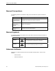
Manual Organzation How To Use This Manual This manual is written for the owner and user of Siemens Building Technologies Actuating Terminal Equipment Controller—Electronic Output, referred to as ATEC for the remainder of this manual. It is designed to help you become familiar with the ATEC and its applications. This section covers manual organization, manual conventions, symbols used in the manual, and other information that will help you use this manual.
How To Use This Manual Manual Conventions The following table lists conventions to help you use this manual in a quick and efficient manner. Convention Example Actions that you should perform are specified in boldface font. Type F for Field panels. Click OK to save changes and close the dialog box. Error and system messages are displayed in Courier New font. The message Report Definition successfully renamed appears in the status bar. New terms appearing for the first time are italicized.
Getting Help Datamate Base works on an IBM-compatible personal computer or a handheld PC or Pocket PC™ running Windows CE. Datamate Advanced works only on an IBM-compatible personal computer. With Datamate, you can back up, restore, and edit any APOGEE® database (but only Datamate Advanced allows you to edit points offline).
How To Use This Manual VIII Siemens Building Technologies, Inc.
Chapter 1—Hardware Chapter Overview Chapter 1 discusses the following topics: • • The Controller − Digital Inputs − Analog Inputs − Digital Outputs − Power Wiring − Communication Wiring − Controller LED Indicator − Damper Actuator − Air Velocity Sensor Temperature Sensors − Room Temperature Sensor − Return-Duct Temperature Sensor − Supply-Duct Temperature Sensor • Autozero Module • Actuators • Relay Module Siemens Building Technologies, Inc.
Chapter 1—Hardware The Controller The Actuating Terminal Equipment Controller (ATEC) is an APOGEE Terminal Equipment Controller (TEC) from Siemens Building Technologies, Inc. It is used in pressure-independent Variable Air Volume (VAV) applications. The ATEC is an electronic-output controller that combines a damper actuator and a TEC into one package. It provides Direct Digital Control (DDC) and can operate independently as a stand-alone DDC room controller or networked with an APOGEE field panel.
The Controller The ATEC with Reheat model (Figure 1-2) is designed to control terminal boxes, either single duct or fan powered (series or parallel), with hot water reheat or up to two stages of electric reheat. It includes Applications 2500, 2501, 2522, 2523, 2524, and 2526. It has removable terminal blocks for FLN, I/O, and power terminations. An Autozero Module can be used with this controller for Applications 2500, 2501, and 2522.
Chapter 1—Hardware Analog Inputs Both models of the controller have Analog Inputs AI 1 and Al 2. Al 1 and Al 2 are used by the room temperature sensor and the setpoint dial respectively. These Als are not wireable and are not available for use as auxiliary analog input points. In addition to AI 1 and AI 2, the ATEC with Reheat includes Al 3 (screw terminals 4 and 5) and AI 4 (terminals 5 and 6). These inputs can be used for auxiliary temperature inputs to the controller by connecting 100K Ω thermistors.
The Controller CONTROLLER POWER WIRING COMMON 24 VAC HOT EARTH GND TEC0467R1 E H C Figure 1-3. ATEC Power Wiring. Communication Wiring + - S The controller connects to the field panel by means of a Floor Level Network (FLN) trunk. Communication wiring connects to the three screw terminals on the controller labeled " + " (positive), "-" (negative), and "S" (Shield) (Figure 1-4). TEC0463R1 (SHIELD) (SHIELD) (-) (+) (-) (+) Figure 1-4. ATEC Communication Wiring.
Chapter 1—Hardware Damper Actuator The ATEC includes an actuator that modulates a damper in the supply duct, adjusting airflow to meet the room’s demand for cooling or heating. For more information, contact your local Siemens Building Technologies representative. Air Velocity Sensor The ATEC includes an air velocity sensor that provides air-velocity inputs to the controller.
Autozero Module Autozero Module The optional Autozero Module (Figure 1-5) is required when continuous operation at occupied flow is required for an area. The Autozero Module is connected to the air velocity inlet ports of the ATEC and provides periodic recalibration of the air velocity sensor without changing air volume being delivered to a room. This recalibration ensures long-term precise airflow delivery.
Chapter 1—Hardware Relay Module WARNING: The relay module is a high voltage device. A Terminal Equipment Controller relay module (Figure 1-6) is used in conjunction with the controller when the following situations are present: • ATEC digital output (DO) is used to drive electric heating coils. • Controlled load is greater than 12 VA. • Controlled load is greater than 24 Vac. • Controlled load is DC. • Controlled load is powered by a transformer other than the one powering the ATEC.
Chapter 2—Applications for ATEC— Base VAV Chapter Overview Chapter 2 discusses the following topics: • Basic Operation of the Actuating Terminal Equipment Controller—Electronic Output • Control Operation of the Actuating Terminal Equipment Controller—Electronic Output • Application Illustrations • Controller Points Applications Overview Page • Application 2520: VAV Cooling Only.........................................................................
Chapter 2—Applications for ATEC—Base VAV Introduction Basic Operation The Actuating Terminal Equipment Controller—Electronic Output (ATEC) provides Direct Digital Control (DDC) for Variable Air Volume (VAV) terminal box applications. Temperature control varies with the application. If present, heating can be provided by hot water, up to two stages of electric reheat, or optional baseboard radiation. Application 2521 requires the central air-handling unit to provide warm air during the heating mode.
Application 2520: VAV Cooling Only Application 2520: VAV Cooling Only Overview In Application 2520, the controller modulates the supply air damper of the terminal box for cooling. In order for it to work properly, the central Air Handling Unit must provide cool supply air. See Figure 2-1 and Figure 2-2. 3 TO 5 STRAIGHT DUCT DIAMETERS REQUIRED FOR PROPER SENSOR READING SUPPLY AIR DAMPER SUPPLY AIR AIR VELOCITY SENSOR ATEC FLN 90 45 TEC0421R1 90 RTS HI/LO Tubing Connections 24VAC Figure 2-1.
Chapter 2—Applications for ATEC—Base VAV 1. See Sequence of Operation, Control Temperature Setpoints. Figure 2-2. Application 2520 Control Schedule. Hardware Inputs Analog • Air velocity sensor • Room temperature sensor • Room temperature setpoint dial (optional) Digital • Night mode override (optional) Hardware Outputs Analog • None Digital • 2-4 Damper actuator (wired internally) Siemens Building Technologies, Inc.
Application 2520: VAV Cooling Only Ordering Notes Actuating Terminal Equipment Controller—Electronic Output Single unit 10-pack 550-400 550-400P10 Contact your local Siemens Building Technologies representative for additional product numbers. Temperature sensor (select one) • Terminal Equipment Controller room temperature sensor • Duct temperature sensor, 10K Ω, TEC (return-duct sensor) 4-inch (10.
Chapter 2—Applications for ATEC—Base VAV Night Mode Override Switch If an override switch is present on the room temperature sensor and a value (in hours) other than zero has been entered into OVRD TIME (Point 20), pressing the override switch resets the controller to day operational mode for the time period that is set in OVRD TIME. The status of NGT OVRD (Point 21) changes to DAY. After the override time elapses, the controller returns to night mode and NGT OVRD changes back to NIGHT.
Application 2520: VAV Cooling Only Automated Checkout The ATEC has a built-in checkout procedure that can be manually initiated at any time after the controller has been installed. The procedure tests all of the necessary I/O and ensures the controller has the ability to operate within the set airflow range, between CLG FLOW MIN (Point 31) and CLG FLOW MAX (Point 32). To perform the checkout procedure, set CHK OUT (Point 10) to YES.
Chapter 2—Applications for ATEC—Base VAV Wiring Diagram The point wiring for Application 2520 is shown in Figure 2-3. FLN 90 45 90 RTS Lo TEC0419R1 Hi 24 Vac Figure 2-3. Application 2520 Wiring Diagram. 2-8 Siemens Building Technologies, Inc.
Application 2520: VAV Cooling Only Point Database Table 2-2. Point Database for Application 2520. Slope Intercept On Text (SI Units) (SI Units) Off Text Point Number Descriptor Factory Default (SI Units) Eng. Units (SI Units) 01 CTLR ADDRESS 99 – 1 0 – – 02 APPLICATION 2486 – 1 0 – – {03} CHK STATUS -1 – 1 -1 – – {04} ROOM TEMP 74.0 (23.44888) DEG F (DEG C) 0.25 (0.14) 48.0 (8.88888) – – 06 DAY CLG STPT 74.0 (23.44888) DEG F (DEG C) 0.25 (0.14) 48.0 (8.
Chapter 2—Applications for ATEC—Base VAV Table 2-2. Point Database for Application 2520. Point Number Descriptor Factory Default (SI Units) Eng. Units (SI Units) {48} DMPR COMD 0.0 PCT 0.4 0.0 – – {49} DMPR POS 0.0 PCT 0.4 0.0 – – 51 MTR1 TIMING 95 SEC 1 0 – – 56 DMPR ROT ANG 90 – 1 0 – – 58 MTR SETUP 0 – 1 0 – – 59 DO DIR. REV 0 – 1 0 – – 63 CLG P GAIN 20.0 (36.0) – 0.25 (0.45) 0.0 – – 64 CLG I GAIN 0.01 (0.018) – 0.001 (0.0018) 0.
Application 2520: VAV Cooling Only Table 2-2. Point Database for Application 2520. Point Number Descriptor Factory Default (SI Units) Eng. Units (SI Units) 97 DUCT AREA 1.0 (0.09292) SQ. FT (SQ M) 0.025 (0.002323) 0.0 – – 98 LOOP TIME 5 SEC 1 0 – – {99} ERROR STATUS 0 – 1 0 – – 1. 2. 3.
Chapter 2—Applications for ATEC—Base VAV Application 2521: VAV Cooling or Heating Overview In Application 2521, the controller modulates the supply air damper of the terminal box for cooling and heating. In order for it to work properly, the central Air Handling Unit must provide cool supply air in cooling mode and warm air in heating mode. See Figure 2-4 and Figure 2-5.
Application 2521: VAV Cooling or Heating 1. 2. See Sequence of Operation, Control Temperature Setpoints. See Sequence of Operation, Heating/Cooling Switchover. Figure 2-5. Application 2521 Control Schedule. Hardware Inputs Analog • Air velocity sensor • Room temperature sensor • Room temperature setpoint dial (optional) Digital • Night mode override (optional) Hardware Outputs Analog • None Digital • Damper actuator (wired internally) Siemens Building Technologies, Inc.
Chapter 2—Applications for ATEC—Base VAV Ordering Notes Actuating Terminal Equipment Controller—Electronic Output Single unit 10-pack 550-400 550-400P10 Contact your local Siemens Building Technologies representative for additional product numbers. Temperature sensor (select one) • Terminal Equipment Controller room temperature sensor • Duct temperature sensor, 10K Ω, TEC (return-duct sensor) 4-inch (10.
Application 2521: VAV Cooling or Heating Night Mode Override Switch If an override switch is present on the room temperature sensor and a value (in hours) other than zero has been entered into OVRD TIME (Point 20), pressing the override switch resets the controller to day operational mode for the time period that is set in OVRD TIME. The status of NGT OVRD (Point 21) changes to DAY. After the override time elapses, the controller returns to night mode and NGT OVRD changes back to NIGHT.
Chapter 2—Applications for ATEC—Base VAV Calibration Calibration of the controller’s internal air velocity sensor is periodically required to maintain accurate air velocity readings. CAL SETUP (Point 95) is set with the desired calibration option during controller startup. Depending on the value of CAL SETUP, calibration may be set to take place automatically or manually. When CAL AIR (Point 94) has a setting of YES, calibration is in progress.
Application 2521: VAV Cooling or Heating Application Notes 1. If temperature swings in the room are excessive or there is trouble maintaining the setpoint, the cooling loop, the heating loop, or both need to be tuned. If FLOW (Point 75) is oscillating while FLOW STPT (Point 93 is constant, the flow loop requires tuning. Contact your local Siemens Building Technologies representative for more information. 2. The ATEC, as shipped from the factory, keeps all associated equipment off.
Chapter 2—Applications for ATEC—Base VAV Point Database Table 2-4. Point Database for Application 2521. Point Number Descriptor Factory Default (SI Units) Eng. Units (SI Units) Slope (SI Units) Intercept (SI Units) On Text Off Text 01 CTLR ADDRESS 99 – 1 0 – – 02 APPLICATION 2486 – 1 0 – – {03} CHK STATUS -1 – 1 -1 – – {04} ROOM TEMP 74.0 (23.44888) DEG F (DEG C) 0.25 (0.14) 48.0 (8.88888) – – {05} HEAT.COOL COOL – – – HEAT COOL 06 DAY CLG STPT 74.0 (23.
Application 2521: VAV Cooling or Heating Table 2-4. Point Database for Application 2521. Point Number Descriptor Factory Default (SI Units) Eng. Units (SI Units) Slope (SI Units) Intercept (SI Units) On Text Off Text 34 HTG FLOW MAX 2200 (1038.18) CFM (LPS) 4 (1.8876) 0 – – {35} AIR VOLUME 0 (0.0) CFM (LPS) 4 (1.8876) 0 – – 36 FLOW COEFF 1.0 – 0.01 0.0 – – {40} SUPPLY TEMP 74.0 (23.495556) DEG F (DEG C) 0.5 (0.28) 37.5 (3.
Chapter 2—Applications for ATEC—Base VAV Table 2-4. Point Database for Application 2521. Point Number Descriptor Factory Default (SI Units) Eng. Units (SI Units) Slope (SI Units) Intercept (SI Units) On Text Off Text 71 FLOW P GAIN 0.0 – 0.05 0.0 – – 72 FLOW I GAIN 0.01 – 0.001 0.0 – – 73 FLOW D GAIN 0 – 2 0 – – 74 FLOW BIAS 50.0 PCT 0.4 0.0 – – {75} FLOW 0.0 PCT 0.25 0.0 – – {76} CTL FLOW MIN 220 (103.818) CFM (LPS) 4 (1.
Application 2486: Slave Mode Application 2486: Slave Mode Overview Application 2486 is the slave mode application for the ATEC—Electronic Output (P/N 550-400). Slave mode is the default application that comes up when power is first applied to the controller. Slave mode provides no control. Its purpose is to allow the operator to perform equipment checkout before a control application is put into effect and to set some basic controller parameters (CTLR ADDRESS, APPLICATION, etc.).
Chapter 2—Applications for ATEC—Base VAV Point Database Table 2-5. Point Database for Application 2486. Point Number Descriptor Factory Default (SI Units) Eng. Units (SI Units) Slope (SI Units) Intercept (SI Units) On Text Off Text 01 CTLR ADDRESS 99 – 1 0 – – 02 APPLICATION 2486 – 1 0 – – {03} CHK STATUS -1 – 1 -1 – – {04} ROOM TEMP 74.0 (23.44888) DEG F (DEG C) 0.25 (0.14) 48.0 (8.88888) – – {10} CHK OUT NO – – – YES NO {13} RM STPT DIAL 74.0 (23.
Chapter 3—Applications for ATEC—VAV with Reheat Chapter Overview Chapter 3 discusses the following topics: • Basic Operation of the Actuating Terminal Equipment Controller—Electronic Output • Control Operation of the Actuating Terminal Equipment Controller—Electronic Output • Application Illustrations • Controller Points Applications Overview Page • Application 2500: VAV Cooling Only.........................................................................
Chapter 3—Applications for ATEC—VAV with Reheat Introduction Basic Operation The Actuating Terminal Equipment Controller—Electronic Output (ATEC) provides Direct Digital Control (DDC) for Variable Air Volume (VAV) terminal box applications. Temperature control varies with the application. If present, heating can be provided by hot water, up to two stages of electric reheat, or optional baseboard radiation. Application 2501 requires the central air-handling unit to provide warm air during the heating mode.
Application 2500: VAV Cooling Only Application 2500: VAV Cooling Only Overview In Application 2500, the controller modulates the supply air damper of the terminal box for cooling. In order for it to work properly, the central air-handling unit must provide cool supply air. See Figure 3-1 and Figure 3-2. 3 TO 5 STRAIGHT DUCT DIAMETERS REQUIRED FOR PROPER SENSOR READING SUPPLY AIR DAMPER SUPPLY AIR AIR VELOCITY SENSOR ATEC FLN 90 45 90 RTS TEC2500CDR1 Spare DO DO3 Autozero Module (Opt.
Chapter 3—Applications for ATEC—VAV with Reheat 1. See Sequence of Operation, Control Temperature Setpoints. Figure 3-2. Application 2500 Control Schedule. Hardware Inputs Analog • Air velocity sensor • Room temperature sensor • Room temperature setpoint dial (optional) Digital • Night mode override (optional) • Wall switch (optional) Hardware Outputs Analog • None Digital 3-4 • Autozero module (optional) • Damper actuator (wired internally) Siemens Building Technologies, Inc.
Application 2500: VAV Cooling Only Ordering Notes Actuating Terminal Equipment Controller with Reheat—Electronic Output Single unit 10-pack 550-405 550-405P10 Contact your local Siemens Building Technologies, Inc., representative for additional product numbers. Autozero module (optional) Temperature sensor (select one) • Terminal Equipment Controller room temperature sensor • Duct temperature sensor, 10K Ω, TEC (return-duct sensor) 4-inch (10.
Chapter 3—Applications for ATEC—VAV with Reheat If the controller is operating stand-alone, it stays in day mode all the time. If the controller is connected to a field panel, the field panel can send an operator or PPCL command to override the status of DAY.NGT. See the APOGEE® PPCL User’s Manual (125-1896) and Field Panel User’s Manual (125-1895) for more information.
Application 2500: VAV Cooling Only Recalibration of Damper when Autozero Module is Used The Autozero Module is enabled when it is wired to DO 4 and CAL MODULE (Point 87) is set to YES. Under normal operation DMPR STATUS (Point 84) reads CAL. However, if using an Autozero Module, it is possible after a period of operation for the calculated damper position point, DMPR POS (Point 49), to differ from the actual (physical) damper position.
Chapter 3—Applications for ATEC—VAV with Reheat Automated Checkout The ATEC has a built-in checkout procedure that can be manually initiated at any time after the controller has been installed. The procedure tests all of the necessary I/O and ensures the controller has the ability to operate within the set airflow range, between CLG FLOW MIN (Point 31) and CLG FLOW MAX (Point 32). To perform the checkout procedure, set CHK OUT (Point 10) to YES.
Application 2500: VAV Cooling Only Wiring Diagram The point wiring for Application 2500 is shown in Figure 3-3. CAUTION: The controller’s DOs control 24 Vac loads only. The maximum rating is 12 VA for each DO.
Chapter 3—Applications for ATEC—VAV with Reheat Point Database Table 3-2. Point Database for Application 2500. Point Number Descriptor Factory Default (SI Units) Eng. Units (SI Units) Slope (SI Units) Intercept (SI Units) On Text Off Text 01 CTLR ADDRESS 99 – 1 0 – – 02 APPLICATION 2473 – 1 0 – – {03} CHK STATUS -1 – 1 -1 – – {04} ROOM TEMP 74.0 (23.44888) DEG F (DEG C) 0.25 (0.14) 48.0 (8.88888) – – 06 DAY CLG STPT 74.0 (23.44888) DEG F (DEG C) 0.25 (0.14) 48.
Application 2500: VAV Cooling Only Table 3-2. Point Database for Application 2500. Point Number Descriptor Factory Default (SI Units) Eng. Units (SI Units) Slope (SI Units) Intercept (SI Units) On Text Off Text {35} AIR VOLUME 0 (0.0) CFM (LPS) 4 (1.8876) 0 – – 36 FLOW COEFF 1.0 – 0.01 0.0 – – {40} AI 4 74.0 (23.495556) DEG F (DEG C) 0.5 (0.28) 37.5 (3.
Chapter 3—Applications for ATEC—VAV with Reheat Table 3-2. Point Database for Application 2500. Point Number Descriptor Factory Default (SI Units) Eng. Units (SI Units) Slope (SI Units) Intercept (SI Units) On Text Off Text {77} CTL FLOW MAX 2200 (1038.18) CFM (LPS) 4 (1.8876) 0 – – {78} CTL TEMP 74.0 (23.44888) DEG F (DEG C) 0.25 (0.14) 48.0 (8.88888) – – {79} CLG LOOPOUT 0.0 PCT 0.4 0.
Application 2501: VAV Cooling or Heating Application 2501: VAV Cooling or Heating Overview In Application 2501, the controller modulates the supply air damper of the terminal box for cooling and heating. In order for it to work properly, the central air-handling unit must provide cool supply air in cooling mode and warm air in heating mode. See Figure 3-4 and Figure 3-5.
Chapter 3—Applications for ATEC—VAV with Reheat 1. 2. See Sequence of Operation, Control Temperature Setpoints. See Sequence of Operation, Heating/Cooling Switchover. Figure 3-5. Application 2501 Control Schedule.
Application 2501: VAV Cooling or Heating Ordering Notes Actuating Terminal Equipment Controller with Reheat—Electronic Output Single unit 10-pack 550-405 550-405P10 Contact your local Siemens Building Technologies representative for additional product numbers. Autozero module (optional) Duct temperature sensor, 100K Ω (supply-duct sensor, optional) Temperature sensor (select one) • Terminal Equipment Controller room temperature sensor • Duct temperature sensor, 10K Ω, TEC (return-duct sensor) 4-inch (10.
Chapter 3—Applications for ATEC—VAV with Reheat Day and Night Modes The day/night status of the space is determined by the status of DAY.NGT (Point 29). The control of this point differs depending on whether the controller is monitoring the status of a wall switch or is connected to a field panel.
Application 2501: VAV Cooling or Heating 2. If the controller is connected to a field panel, the field panel can command SUPPLY TEMP. When SUPPLY TEMP is commanded below the value of COOL TEMP, the controller sets HEAT.COOL to COOL, switching the controller to cooling mode. When SUPPLY TEMP is commanded above the value of HEAT TEMP, the controller sets HEAT.COOL to HEAT, switching the controller to heating mode. 3.
Chapter 3—Applications for ATEC—VAV with Reheat Recalibration of Damper when Autozero Module is Used The Autozero Module is enabled when it is wired to DO 4 and CAL MODULE (Point 87) is set to YES. Under normal operation DMPR STATUS (Point 84) reads CAL. However, if using an Autozero Module, it is possible after a period of operation for the calculated damper position point, DMPR POS (Point 49), to differ from the actual (physical) damper position.
Application 2501: VAV Cooling or Heating Automated Checkout The ATEC has a built-in checkout procedure that can be manually initiated at any time after the controller has been installed. The procedure tests all of the necessary I/O and ensures the controller has the ability to operate within the set airflow range, between CLG FLOW MIN (Point 31) and CLG FLOW MAX (Point 32). To perform the checkout procedure, set CHK OUT (Point 10) to YES.
Chapter 3—Applications for ATEC—VAV with Reheat Wiring Diagram The point wiring for Application 2501 is shown in Figure 3-6. CAUTION: The controller’s DOs control 24 Vac loads only. The maximum rating is 12 VA for each DO.
Application 2501: VAV Cooling or Heating Point Database Table 3-4. Point Database for Application 2501 Point Number Descriptor Factory Default (SI Units) Eng. Units (SI Units) Slope (SI Units) Intercept (SI Units) On Text Off Text 01 CTLR ADDRESS 99 – 1 0 – – 02 APPLICATION 2473 – 1 0 – – {03} CHK STATUS -1 – 1 -1 – – {04} ROOM TEMP 74.0 (23.44888) DEG F (DEG C) 0.25 (0.14) 48.0 (8.88888) – – {05} HEAT.COOL COOL – – – HEAT COOL 06 DAY CLG STPT 74.0 (23.
Chapter 3—Applications for ATEC—VAV with Reheat Table 3-4. Point Database for Application 2501 Point Number Descriptor Factory Default (SI Units) Eng. Units (SI Units) Slope (SI Units) Intercept (SI Units) On Text Off Text 31 CLG FLOW MIN 220 (103.818) CFM (LPS) 4 (1.8876) 0 – – 32 CLG FLOW MAX 2200 (1038.18) CFM (LPS) 4 (1.8876) 0 – – 33 HTG FLOW MIN 220 (103.818) CFM (LPS) 4 (1.8876) 0 – – 34 HTG FLOW MAX 2200 (1038.18) CFM (LPS) 4 (1.
Application 2501: VAV Cooling or Heating Table 3-4. Point Database for Application 2501 Point Number Descriptor Factory Default (SI Units) Eng. Units (SI Units) Slope (SI Units) Intercept (SI Units) On Text Off Text 65 CLG D GAIN 0 (0.0) – 2 (3.6) 0 – – 66 CLG BIAS 0.0 PCT 0.4 0.0 – – 67 HTG P GAIN 10.0 (18.0) – 0.25 (0.45) 0.0 – – 68 HTG I GAIN 0.01 (0.018) – 0.001 (0.0018) 0.0 – – 69 HTG D GAIN 0 (0.0) – 2 (3.6) 0 – – 70 HTG BIAS 0.0 PCT 0.4 0.
Chapter 3—Applications for ATEC—VAV with Reheat Application 2522: VAV with Electric Reheat or Baseboard Radiation Overview In Application 2522, the controller modulates the supply air damper of the terminal box for cooling and controls stages of electric reheat or baseboard radiation for heating. When in heating, the terminal box either maintains minimum airflow or modulates the supply air damper. In order for the terminal box to work properly, the central air-handling unit must provide supply air.
Application 2522: VAV with Electric Reheat or Baseboard Radiation 3 TO 5 STRAIGHT DUCT DIAMETERS REQUIRED FOR PROPER SENSOR READING SUPPLY AIR DAMPER SUPPLY AIR AIR VELOCITY SENSOR ATEC FLN 90 45 90 RTS Baseboard Valve (2 pos.) TEC2522BCDR2 DO3 Autozero Module (Opt.) DO4 Spare AI/DI AI3 AI4 NO Wall Switch (Opt.) HI/LO Tubing Connections 24VAC Figure 3-8. Application 2522 Control Drawing for Baseboard Radiation. Siemens Building Technologies, Inc.
Chapter 3—Applications for ATEC—VAV with Reheat CONTROL SCHEDULE ROOM TEMPERATURE COLDER COOLING *1 SET POINT HEATING *1 SET POINT WARMER HEAT ON 100% OF TIME CLG FLOW MAX *2 *2 HEAT COOL TEC2522CSR1 *3 HTG FLOW MAX= HTG FLOW MIN= CLG FLOW MIN= 1. 2. 3. 4. *4 HEAT OFF See Sequence of Operation, Control Temperature Setpoints. See Sequence of Operation, Heating/Cooling Switchover. When temperature is near the setpoint, heat is cycled on and off according to the size of the demand.
Application 2522: VAV with Electric Reheat or Baseboard Radiation Hardware Inputs Analog • Air velocity sensor • Room temperature sensor • Room temperature setpoint dial (optional) Digital • Night mode override (optional) • Wall switch (optional) Hardware Outputs Analog • None Digital • Autozero Module (optional) • Damper actuator (wired internally) • Stage 1 electric reheat or 2-position heating valve • Stage 2 electric reheat (optional) or Autozero module (optional) Ordering Notes Act
Chapter 3—Applications for ATEC—VAV with Reheat Sequence of Operation Control Temperature Setpoints Depending on the controller’s current operational mode (day or night), CTL STPT (Point 92) holds the value of one of the following setpoints: Day Mode—CTL STPT holds the value of DAY CLG STPT (Point 6) or DAY HTG STPT (Point 7). If the room temperature sensor has a setpoint dial and STPT DIAL (Point 14) is set to YES, CTL STPT holds the value of RM STPT DIAL (Point 13).
Application 2522: VAV with Electric Reheat or Baseboard Radiation It is only when the controller is in night mode that the override switch on the room sensor has any effect on the controller. Heating/Cooling Switchover Based on Room Temperature (Internal Logic) The heating/cooling switchover determines whether the controller is in heating or cooling mode by monitoring the room temperature and the demand for heating and cooling (as determined by the temperature control loops).
Chapter 3—Applications for ATEC—VAV with Reheat Control Loops The terminal box is controlled by three Proportional, Integral, and Derivative (PID) control loops: two temperature loops and a flow loop. The two temperature loops are a cooling loop and a heating loop. The active temperature loop maintains room temperature at the value in CTL STPT (Point 92). See Control Temperature Setpoints (page 3-28).
Application 2522: VAV with Electric Reheat or Baseboard Radiation Electric Reheat CAUTION: Verify that the equipment is supplied with safeties by others to ensure that there is airflow across the heating coils when they are to be energized. CAUTION: Do not set HTG FLOW MIN (Point 33) to 0 cfm (0 lps). A minimum airflow should be provided across the heating coils, for ventilation and for dispersing heat. The heating loop controls up to two stages of electric reheat to warm up the room.
Chapter 3—Applications for ATEC—VAV with Reheat The damper moves from minimum position to fully open as HTG LOOPOUT increases from FLOW START to FLOW END. If FLOW START and FLOW END are both set to 0% (default value), the damper stays at minimum position while in heating mode. The cycle for the reheat ranges from always off to always on as HTG LOOPOUT increases from REHEAT START to REHEAT END. Default values for these points are 0% and 100% respectively.
Application 2522: VAV with Electric Reheat or Baseboard Radiation Recalibration of Damper when Autozero Module is Used The Autozero Module is enabled when it is wired to DO 4 and CAL MODULE (Point 87) is set to YES. Under normal operation DMPR STATUS (Point 84) reads CAL. However, if using an Autozero Module, it is possible after a period of operation for the calculated damper position point, DMPR POS (Point 49), to differ from the actual (physical) damper position.
Chapter 3—Applications for ATEC—VAV with Reheat Automated Checkout The ATEC has a built-in checkout procedure that can be manually initiated at any time after the controller has been installed. The procedure tests all of the necessary I/O and ensures the controller has the ability to operate within the set airflow range, between CLG FLOW MIN (Point 31) and CLG FLOW MAX (Point 32). To perform the checkout procedure, set CHK OUT (Point 10) to YES.
Application 2522: VAV with Electric Reheat or Baseboard Radiation Wiring Diagram The point wiring for Application 2522 is shown in Figure 3-11. CAUTION: The controller’s DOs control 24 Vac loads only. The maximum rating is 12 VA for each DO.
Chapter 3—Applications for ATEC—VAV with Reheat Point Database Table 3-6. Point Database for Application 2522. Point Number Descriptor Factory Default (SI Units) Eng. Units (SI Units) Slope (SI Units) Intercept (SI Units) On Text Off Text 01 CTLR ADDRESS 99 – 1 0 – – 02 APPLICATION 2473 – 1 0 – – {03} CHK STATUS -1 – 1 -1 – – {04} ROOM TEMP 74.0 (23.44888) DEG F (DEG C) 0.25 (0.14) 48.0 (8.88888) – – {05} HEAT.COOL COOL – – – HEAT COOL 06 DAY CLG STPT 74.
Application 2522: VAV with Electric Reheat or Baseboard Radiation Table 3-6. Point Database for Application 2522. Point Number Descriptor Factory Default (SI Units) Eng. Units (SI Units) Slope (SI Units) Intercept (SI Units) On Text Off Text 23 REHEAT END 100.0 PCT 0.4 0.0 – – {24} DI 4 OFF – – – ON OFF {25} DI 3 OFF – – – ON OFF {29} DAY.NGT DAY – – – NIGHT DAY 31 CLG FLOW MIN 220 (103.818) CFM (LPS) 4 (1.8876) 0 – – 32 CLG FLOW MAX 2200 (1038.
Chapter 3—Applications for ATEC—VAV with Reheat Table 3-6. Point Database for Application 2522. Point Number Descriptor Factory Default (SI Units) Eng. Units (SI Units) Slope (SI Units) Intercept (SI Units) On Text Off Text 68 HTG I GAIN 0.01 (0.018) – 0.001 (0.0018) 0.0 – – 69 HTG D GAIN 0 (0.0) – 2 (3.6) 0 – – 70 HTG BIAS 0.0 PCT 0.4 0.0 – – 71 FLOW P GAIN 0.0 – 0.05 0.0 – – 72 FLOW I GAIN 0.01 – 0.001 0.
Application 2522: VAV with Electric Reheat or Baseboard Radiation Table 3-6. Point Database for Application 2522. Point Number Descriptor Factory Default (SI Units) Eng. Units (SI Units) Slope (SI Units) Intercept (SI Units) On Text Off Text 95 CAL SETUP 4 – 1 0 – – 96 CAL TIMER 12 HRS 1 0 – – 97 DUCT AREA 1.0 (0.09292) SQ. FT (SQ M) 0.025 (0.002323) 0.0 – – 98 LOOP TIME 5 SEC 1 0 – – {99} ERROR STATUS 0 – 1 0 – – 1. 2. 3.
Chapter 3—Applications for ATEC—VAV with Reheat Application 2523: VAV with Hot Water Reheat (only one reheat valve) Overview In Application 2523, the controller modulates the supply air damper of the terminal box for cooling and modulates a reheat valve for heating. When in heating, the terminal box either maintains minimum airflow or modulates the supply air damper. In order for the terminal box to work properly, the central air-handling unit must provide supply air. See Figure 3-12 through Figure 3-14.
Application 2523: VAV with Hot Water Reheat (only one reheat valve) CONTROL SCHEDULE ROOM TEMPERATURE COLDER COOLING *1 SET POINT HEATING *1 SET POINT WARMER HEAT ON 100% OF TIME CLG FLOW MAX *2 *2 HEAT COOL TEC2523CSR1 *3 HTG FLOW MAX= HTG FLOW MIN= CLG FLOW MIN= 1. 2. 3. 4. *4 HEAT OFF See Sequence of Operation, Control Temperature Setpoints. See Sequence of Operation, Heating/Cooling Switchover. When temperature is near the setpoint, heat is modulated according to the size of the demand.
Chapter 3—Applications for ATEC—VAV with Reheat Hardware Inputs Analog • Air velocity sensor • Room temperature sensor • Room temperature setpoint dial (optional) Digital • Night mode override (optional) • Wall switch (optional) Hardware Outputs Analog • None Digital • Damper actuator (wired internally) • Valve actuator (required) Ordering Notes Actuating Terminal Equipment Controller with Reheat—Electronic Output Single unit 10-pack 550-405 550-405P10 Contact your local Siemens Building
Application 2523: VAV with Hot Water Reheat (only one reheat valve) Sequence of Operation Control Temperature Setpoints Depending on the controller’s current operational mode (day or night), CTL STPT (Point 92) holds the value of one of the following setpoints: Day Mode—CTL STPT holds the value of DAY CLG STPT (Point 6) or DAY HTG STPT (Point 7). If the room temperature sensor has a setpoint dial and STPT DIAL (Point 14) is set to YES, CTL STPT holds the value of RM STPT DIAL (Point 13).
Chapter 3—Applications for ATEC—VAV with Reheat Night Mode Override Switch If an override switch is present on the room temperature sensor and a value (in hours) other than zero has been entered into OVRD TIME (Point 20), pressing the override switch resets the controller to day operational mode for the time period that is set in OVRD TIME. The status of NGT OVRD (Point 21) changes to DAY. After the override time elapses, the controller returns to night mode and NGT OVRD changes back to NIGHT.
Application 2523: VAV with Hot Water Reheat (only one reheat valve) Control Loops The terminal box is controlled by three Proportional, Integral, and Derivative (PID) control loops: two temperature loops and a flow loop. The two temperature loops are a cooling loop and a heating loop. The active temperature loop maintains room temperature at the value in CTL STPT (Point 92). See Control Temperature Setpoints (page 3-43).
Chapter 3—Applications for ATEC—VAV with Reheat Sequencing Logic (Optional) The settings of FLOW START (Point 16), FLOW END (Point 17), REHEAT START (Point 22), and REHEAT END (Point 23) determine how the damper and reheat modulation are sequenced while in heating mode. These points represent the values of HTG LOOPOUT (Point 80) at which modulation of the damper and reheat begin and end. The damper moves from minimum position to fully open as HTG LOOPOUT increases from FLOW START to FLOW END.
Application 2523: VAV with Hot Water Reheat (only one reheat valve) Automated Checkout The ATEC has a built-in checkout procedure that can be manually initiated at any time after the controller has been installed. The procedure tests all of the necessary I/O and ensures the controller has the ability to operate within the set airflow range, between CLG FLOW MIN (Point 31) and CLG FLOW MAX (Point 32). To perform the checkout procedure, set CHK OUT (Point 10) to YES.
Chapter 3—Applications for ATEC—VAV with Reheat Wiring Diagram The point wiring for Application 2523 is shown in Figure 3-15. CAUTION: The controller’s DOs control 24 Vac loads only. The maximum rating is 12 VA for each DO.
Application 2523: VAV with Hot Water Reheat (only one reheat valve) Point Database Table 3-8. Point Database for Application 2523. Point Number Descriptor Factory Default (SI Units) Eng. Units (SI Units) Slope (SI Units) Intercept (SI Units) On Text Off Text 01 CTLR ADDRESS 99 – 1 0 – – 02 APPLICATION 2473 – 1 0 – – {03} CHK STATUS -1 – 1 -1 – – {04} ROOM TEMP 74.0 (23.44888) DEG F (DEG C) 0.25 (0.14) 48.0 (8.88888) – – {05} HEAT.
Chapter 3—Applications for ATEC—VAV with Reheat Table 3-8. Point Database for Application 2523. Point Number Descriptor Factory Default (SI Units) Eng. Units (SI Units) Slope (SI Units) Intercept (SI Units) On Text Off Text 22 REHEAT START 0.0 PCT 0.4 0.0 – – 23 REHEAT END 100.0 PCT 0.4 0.0 – – {24} DI 4 OFF – – – ON OFF {25} DI 3 OFF – – – ON OFF {29} DAY.NGT DAY – – – NIGHT DAY 31 CLG FLOW MIN 220 (103.818) CFM (LPS) 4 (1.
Application 2523: VAV with Hot Water Reheat (only one reheat valve) Table 3-8. Point Database for Application 2523. Point Number Descriptor Factory Default (SI Units) Eng. Units (SI Units) Slope (SI Units) Intercept (SI Units) On Text Off Text 64 CLG I GAIN 0.01 (0.018) – 0.001 (0.0018) 0.0 – – 65 CLG D GAIN 0 (0.0) – 2 (3.6) 0 – – 66 CLG BIAS 0.0 PCT 0.4 0.0 – – 67 HTG P GAIN 10.0 (18.0) – 0.25 (0.45) 0.0 – – 68 HTG I GAIN 0.01 (0.018) – 0.001 (0.0018) 0.
Chapter 3—Applications for ATEC—VAV with Reheat Table 3-8. Point Database for Application 2523. Point Number Descriptor Factory Default (SI Units) Eng. Units (SI Units) Slope (SI Units) Intercept (SI Units) On Text Off Text 97 DUCT AREA 1.0 (0.09292) SQ. FT (SQ M) 0.025 (0.002323) 0.0 – – 98 LOOP TIME 5 SEC 1 0 – – {99} ERROR STATUS 0 – 1 0 – – 1. 2. 3.
Application 2524: VAV Series Fan Powered with One Stage of Electric Reheat Application 2524: VAV Series Fan Powered with One Stage of Electric Reheat Overview In Application 2524, the controller modulates the supply air damper of the terminal box for cooling and controls one stage of electric reheat for heating. When in heating, the terminal box either maintains minimum airflow or modulates the supply air damper. The terminal box also has a series fan for air circulation.
Chapter 3—Applications for ATEC—VAV with Reheat CONTROL SCHEDULE ROOM TEMPERATURE COOLING *1 SET POINT HEATING *1 SET POINT COLDER WARMER HEAT ON 100% OF TIME CLG FLOW MAX *2 *2 HEAT COOL TEC2524CSR1 *3 HTG FLOW MAX= HTG FLOW MIN= CLG FLOW MIN= *4 HEAT OFF FAN OPERATION - DAY ON FAN OPERATION - NIGHT 1. 2. 3. 4. ON OFF ON See Sequence of Operation, Control Temperature Setpoints. See Sequence of Operation, Heating/Cooling Switchover.
Application 2524: VAV Series Fan Powered with One Stage of Electric Reheat Hardware Inputs Analog • Air velocity sensor • Room temperature sensor • Room temperature setpoint dial (optional) Digital • Night mode override (optional) • Wall switch (optional) Hardware Outputs Analog • None Digital • Damper actuator (wired internally) • Series fan • Stage 1 electric reheat Ordering Notes Actuating Terminal Equipment Controller with Reheat—Electronic Output Single unit 10-pack 550-405 550-405P
Chapter 3—Applications for ATEC—VAV with Reheat Sequence of Operation Control Temperature Setpoints Depending on the controller’s current operational mode (day or night), CTL STPT (Point 92) holds the value of one of the following setpoints: Day Mode—CTL STPT holds the value of DAY CLG STPT (Point 6) or DAY HTG STPT (Point 7). If the room temperature sensor has a setpoint dial and STPT DIAL (Point 14) is set to YES, CTL STPT holds the value of RM STPT DIAL (Point 13).
Application 2524: VAV Series Fan Powered with One Stage of Electric Reheat Night Mode Override Switch If an override switch is present on the room temperature sensor and a value (in hours) other than zero has been entered into OVRD TIME (Point 20), pressing the override switch resets the controller to day operational mode for the amount of time set in OVRD TIME. The status of NGT OVRD (Point 21) changes to DAY.
Chapter 3—Applications for ATEC—VAV with Reheat Control Loops The terminal box is controlled by three Proportional, Integral, and Derivative (PID) control loops: two temperature loops and a flow loop. The two temperature loops are a cooling loop and a heating loop. The active temperature loop maintains room temperature at the value in CTL STPT (Point 92). See Control Temperature Set Points (page 3-56).
Application 2524: VAV Series Fan Powered with One Stage of Electric Reheat Example Assume the duty cycle (STAGE TIME, Point 89) is 10 minutes, REHEAT START (Point 22) is 0%, and REHEAT END (Point 23) is 100%. The following table shows the intervals during which heat is on and off for various levels of demand from the heating loopout (HTG LOOPOUT, Point 80).
Chapter 3—Applications for ATEC—VAV with Reheat Fan Operation CAUTION: On a terminal box with a series fan, the terminal box fan must be controlled/interlocked to start either before or at the same time as the central air handler. Failure to do so may cause the terminal box fan to rotate backwards and cause consequent damage at start up. Day Mode—FAN (Point 44) is ON all of the time.
Application 2524: VAV Series Fan Powered with One Stage of Electric Reheat To perform the checkout procedure, set CHK OUT (Point 10) to YES. When the procedure is completed, CHK OUT returns to NO and the results are displayed in CHK STATUS (Point 3). See Table 3-9. Table 3-9. Possible Failure Value and Description. CHK STATUS Values (Point 3) -1 NOTE: Description Checkout procedure has not been run since last controller initialization. 0 No errors found. 1 Room temperature sensor failed.
Chapter 3—Applications for ATEC—VAV with Reheat Wiring Diagram Figure 3-19 shows the point wiring for Application 2524. CAUTION: The controller’s DOs control 24 Vac loads only. The maximum rating is 12 VA for each DO.
Application 2524: VAV Series Fan Powered with One Stage of Electric Reheat Point Database Table 3-10. Point Database for Application 2524 Point Number Descriptor Factory Default (SI Units) Eng. Units (SI Units) Slope (SI Units) Intercept (SI Units) On Text Off Text 01 CTLR ADDRESS 99 – 1 0 – – 02 APPLICATION 2473 – 1 0 – – {03} CHK STATUS -1 – 1 -1 – – {04} ROOM TEMP 74.0 (23.44888) DEG F (DEG C) 0.25 (0.14) 48.0 (8.88888) – – {05} HEAT.
Chapter 3—Applications for ATEC—VAV with Reheat Table 3-10. Point Database for Application 2524 Point Number Descriptor Factory Default (SI Units) Eng. Units (SI Units) Slope (SI Units) Intercept (SI Units) On Text Off Text 23 REHEAT END 100.0 PCT 0.4 0.0 – – {24} DI 4 OFF – – – ON OFF {25} DI 3 OFF – – – ON OFF 26 SERIES ON 20.0 PCT 0.4 0.0 – – 27 SERIES OFF 10.0 PCT 0.4 0.0 – – 28 PARALLEL ON 20.0 PCT 0.4 0.0 – – {29} DAY.
Application 2524: VAV Series Fan Powered with One Stage of Electric Reheat Table 3-10. Point Database for Application 2524 Point Number Descriptor Factory Default (SI Units) Eng. Units (SI Units) Slope (SI Units) Intercept (SI Units) On Text Off Text 64 CLG I GAIN 0.01 (0.018) – 0.001 (0.0018) 0.0 – – 65 CLG D GAIN 0 (0.0) – 2 (3.6) 0 – – 66 CLG BIAS 0.0 PCT 0.4 0.0 – – 67 HTG P GAIN 10.0 (18.0) – 0.25 (0.45) 0.0 – – 68 HTG I GAIN 0.01 (0.018) – 0.001 (0.
Chapter 3—Applications for ATEC—VAV with Reheat Table 3-10. Point Database for Application 2524 Point Number Descriptor Factory Default (SI Units) Eng. Units (SI Units) Slope (SI Units) Intercept (SI Units) On Text Off Text {92} CTL STPT 74.0 (23.44888) DEG F (DEG C) 0.25 (0.14) 48.0 (8.88888) – – {93} FLOW STPT 0.0 PCT 0.25 0.0 – – {94} CAL AIR NO – – – YES NO 95 CAL SETUP 4 – 1 0 – – 96 CAL TIMER 12 HRS 1 0 – – 97 DUCT AREA 1.0 (0.09292) SQ.
Application 2526: VAV Parallel Fan Powered with One Stage of Electric Reheat Application 2526: VAV Parallel Fan Powered with One Stage of Electric Reheat Overview In Application 2526, the controller modulates the supply air damper of the terminal box for cooling and controls one stage of electric reheat for heating. When in heating, the terminal box either maintains minimum airflow or modulates the supply air damper. The terminal box also has a parallel fan that recirculates the room air.
Chapter 3—Applications for ATEC—VAV with Reheat CONTROL SCHEDULE ROOM TEMPERATURE COOLING *1 SET POINT HEATING *1 SET POINT COLDER WARMER HEAT ON 100% OF TIME CLG FLOW MAX *2 HEAT *2 COOL TEC2526CSR1 *3 HTG FLOW MAX= HTG FLOW MIN= CLG FLOW MIN= *4 HEAT OFF FAN OPERATION - DAY ON OFF FAN OPERATION - NIGHT ON OFF 1. 2. 3. 4. See Sequence of Operation, Control Temperature Setpoints. See Sequence of Operation, Heating/Cooling Switchover.
Application 2526: VAV Parallel Fan Powered with One Stage of Electric Reheat Hardware Inputs Analog • Air velocity sensor • Room temperature sensor • Room temperature setpoint dial (optional) Digital • Night mode override (optional) • Wall switch (optional) Hardware Outputs Analog • None Digital • Damper actuator (wired internally) • Parallel fan • Stage 1 electric reheat Ordering Notes Actuating Terminal Equipment Controller with Reheat—Electronic Output Single unit 10-pack 550-405 550-
Chapter 3—Applications for ATEC—VAV with Reheat Sequence of Operation Control Temperature Setpoints Depending on the controller’s current operational mode (day or night), CTL STPT (Point 92) holds the value of one of the following setpoints: Day Mode—CTL STPT holds the value of DAY CLG STPT (Point 6) or DAY HTG STPT (Point 7). If the room temperature sensor has a setpoint dial and STPT DIAL (Point 14) is set to YES, CTL STPT holds the value of RM STPT DIAL (Point 13).
Application 2526: VAV Parallel Fan Powered with One Stage of Electric Reheat Night Mode Override Switch If an override switch is present on the room temperature sensor and a value (in hours) other than zero is entered into OVRD TIME (Point 20), pressing the override switch resets the controller to day operational mode of the time period that is set in OVRD TIME. The status of NGT OVRD (Point 21) changes to DAY.
Chapter 3—Applications for ATEC—VAV with Reheat Control Loops The terminal box is controlled by three Proportional, Integral, and Derivative (PID) control loops: two temperature loops and a flow loop. The two temperature loops are a cooling loop and a heating loop. The active temperature loop maintains room temperature at the value in CTL STPT (Point 92). See Control Temperature Setpoints (page 3-70).
Application 2526: VAV Parallel Fan Powered with One Stage of Electric Reheat Electric Reheat CAUTION: Verify that the equipment is supplied with safeties by others to ensure that there is airflow across the heating coils when they are to be energized. CAUTION: Do not set HTG FLOW MIN (Point 33) to 0 cfm (0 lps). A minimum airflow should be provided across the heating coils, for ventilation and for dispersing heat. The heating loop controls one stage of electric reheat to warm up the room.
Chapter 3—Applications for ATEC—VAV with Reheat By varying the values of these start and end points, the damper and the reheat can be sequenced in series, parallel, or overlapping, as shown in the following table: Series Parallel Overlapping Minimum Flow (Default Value) FLOW START 0% 0% 0% 0% FLOW END 50% 100% 75% 0% REHEAT START 50% 0% 25% 0% REHEAT END 100% 100% 100% 100% Calibration of Air Velocity Sensor Calibration of the controller’s internal air velocity sensor is periodicall
Application 2526: VAV Parallel Fan Powered with One Stage of Electric Reheat Fail-safe Operation If the air velocity sensor fails, the controller uses pressure-dependent control. The temperature loop controls the operation of the damper. If the room temperature sensor fails, the controller operates using the last known temperature value. Automated Checkout The ATEC has a built-in checkout procedure that can be manually initiated at any time after the controller has been installed.
Chapter 3—Applications for ATEC—VAV with Reheat Wiring Diagram Figure 3-23 shows the point wiring for Application 2526. CAUTION: The controller’s DOs control 24 Vac loads only. The maximum rating is 12 VA for each DO.
Application 2526: VAV Parallel Fan Powered with One Stage of Electric Reheat Point Database Table 3-12. Point Database for Application 2526. Point Number 1. 2. 3. Descriptor Factory Default (SI Units) Eng. Units (SI Units) Slope (SI Units) Intercept (SI Units) On Text Off Text 99 – 1 0 – – 01 CTLR ADDRESS 02 APPLICATION 2473 – 1 0 – – {03} CHK STATUS -1 – 1 -1 – – {04} ROOM TEMP 74.0 (23.44888) DEG F (DEG C) 0.25 (0.14) 48.0 (8.88888) – – {05} HEAT.
Chapter 3—Applications for ATEC—VAV with Reheat Table 3-12. Point Database for Application 2526. Point Number Descriptor Factory Default (SI Units) Eng. Units (SI Units) Slope (SI Units) Intercept (SI Units) On Text Off Text 23 REHEAT END 100.0 PCT 0.4 0.0 – – {24} DI 4 OFF – – – ON OFF {25} DI 3 OFF – – – ON OFF 26 SERIES ON 20.0 PCT 0.4 0.0 – – 27 SERIES OFF 10.0 PCT 0.4 0.0 – – 28 PARALLEL ON 20.0 PCT 0.4 0.0 – – {29} DAY.
Application 2526: VAV Parallel Fan Powered with One Stage of Electric Reheat Table 3-12. Point Database for Application 2526. Point Number Descriptor Factory Default (SI Units) Eng. Units (SI Units) Slope (SI Units) Intercept (SI Units) On Text Off Text 64 CLG I GAIN 0.01 (0.018) – 0.001 (0.0018) 0.0 – – 65 CLG D GAIN 0 (0.0) – 2 (3.6) 0 – – 66 CLG BIAS 0.0 PCT 0.4 0.0 – – 67 HTG P GAIN 10.0 (18.0) – 0.25 (0.45) 0.0 – – 68 HTG I GAIN 0.01 (0.018) – 0.001 (0.
Chapter 3—Applications for ATEC—VAV with Reheat Table 3-12. Point Database for Application 2526. Point Number Descriptor Factory Default (SI Units) Eng. Units (SI Units) Slope (SI Units) Intercept (SI Units) On Text Off Text {92} CTL STPT 74.0 (23.44888) DEG F (DEG C) 0.25 (0.14) 48.0 (8.88888) – – {93} FLOW STPT 0.0 PCT 0.25 0.0 – – {94} CAL AIR NO – – – YES NO 95 CAL SETUP 4 – 1 0 – – 96 CAL TIMER 12 HRS 1 0 – – 97 DUCT AREA 1.0 (0.09292) SQ.
Application 2473: Slave Mode Application 2473: Slave Mode Overview Application 2473 is the slave mode application for the ATEC with Reheat (P/N 550-405). Slave mode is the default application that comes up when power is first applied to the controller. Slave mode provides no control. Its purpose is to allow the operator to perform equipment checkout before a control application is put into effect and to set some basic controller parameters (CTLR ADDRESS, APPLICATION, etc.).
Chapter 3—Applications for ATEC—VAV with Reheat Example If using DO 3 and DO 4 as the physical terminations for a motor, follow these steps: 1. Set MTR SETUP as per Table 3-13 to enable both Motor 1 (the damper) and Motor 2. 2. Unbundle MTR2 COMD at the field panel to command the motor from the field panel. For other combinations of DOs and motors, contact you local Siemens Building Technologies representative for complete motor enable/reverse procedures. Point Database Table 3-14.
Application 2473: Slave Mode Table 3-14. Point Database for Application 2473. Point Number Descriptor Factory Default (SI Units) Eng. Units (SI Units) Slope (SI Units) Intercept (SI Units) {43} DO 3 OFF – – – ON OFF {44} DO 4 OFF – – – ON OFF {48} MTR1 COMD 0.0 PCT 0.4 0.0 – – {49} MTR1 POS 0.0 PCT 0.4 0.0 – – 51 MTR1 TIMING 95 SEC 1 0 – – {52} MTR2 COMD 0.0 PCT 0.4 0.0 – – {53} MTR2 POS 0.0 PCT 0.4 0.
Chapter 3—Applications for ATEC—VAV with Reheat 3-84 Siemens Building Technologies, Inc.
Chapter 4—Point Database Overview Chapter 4 presents a description of the ATEC point database, including point descriptors, point addresses, and a listing of applications in which each point is found. Applications in parentheses are slave modes. Description of Points Descriptor Address Application Description CTLR ADDRESS 01 All Identifies the controller on the FLN trunk. Addresses 0 to 98 are valid; 0 to 31 are typically used.
Chapter 4—Point Database Descriptor Address Application Description RM STPT MAX 12 All except slave modes The maximum temperature setpoint in degrees that the controller can use from the setpoint dial. This overrides any temperature setpoint from the setpoint dial that falls above this maximum. RM STPT DIAL 13 All The temperature setpoint in degrees from the room temperature sensor (not available on all temperature sensor models).
Description of Points Descriptor Address Application Description NGT OVRD 21 All except slave modes Indicates the mode that the controller is operating in with respect to the override switch. NIGHT indicates that the switch has not been pressed and the override timer is not active. DAY indicates that the switch has been pressed and the override timer is active. The controller then uses a day mode temperature setpoint. This point is only in effect when DAY.NGT (Point 29) indicates night mode.
Chapter 4—Point Database Descriptor Address Application HTG FLOW MIN 33 2501, 2521, 2522, 2523, 2524, 2526 The minimum amount of air in cfm (lps) to be supplied to the space in heating mode. HTG FLOW MAX 34 2501, 2521, 2522, 2523, 2524, 2526 The maximum amount of air in cfm (lps) to be supplied to the space in heating mode. AIR VOLUME 35 All Actual amount of air in cfm (lps) currently passing through the air velocity sensor. FLOW COEFF 36 All Calibration factor for the airflow sensor.
Description of Points Descriptor Address Application Description DMPR POS 49 All except slave modes MTR1 POS 49 (2473), (2486) MTR1 TIMING 51 All MTR2 COMD 52 2500, 2501, (2473) VLV COMD 52 2523 MTR2 POS 53 2500, 2501, (2473) The current position of the Motor 2 actuator in percent of full travel (for use as an auxiliary slave point). This value is calculated based on motor run time. See MTR2 TIMING (Point 55).
Chapter 4—Point Database Descriptor Address Application CLG D GAIN 65 All except slave modes The derivative gain value for the cooling temperature control loop. CLG BIAS 66 All except slave modes The biasing of the cooling temperature control loop. See CLG LOOPOUT (Point 79). HTG P GAIN 67 2501, 2521, 2522, 2523, 2524, 2526 The proportional gain value for the heating temperature control loop.
Description of Points Descriptor Address Application Description AVG HEAT OUT 81 2522, 2524, 2526 This point is used to determine what stages of electric heat are used for a given loop output value. The ranges for the value are determined by the number of stages used: 0 to 100 for 1 stage of electric heat, and 0 to 200 for 2 stages of electric heat. For example, a value of 150 indicates that Stage 1 is on 100% of the time and Stage 2 is on 50% of the time.
Chapter 4—Point Database Descriptor Address Application Description SWITCH DBAND 90 2522, 2523, 2524, 2526 The temperature range in degrees which is compared to the difference between CTL TEMP (Point 78) and CTL STPT (Point 92). The difference must exceed this value for temperature control mode to change over between heating and cooling. Changeover is also subject to the active temperature control loop output being below SWITCH LIMIT (Point 85) and SWITCH TIME (Point 86) being expired.
Chapter 5—Troubleshooting Overview Chapter 5 discusses the following topics: Page • Basics of Troubleshooting................................................................................................. 5-2 − Datamate Software..................................................................................................... 5-2 − Basic Service Information........................................................................................... 5-2 − Preventive Maintenance .........................
Chapter 5—Troubleshooting Basics of Troubleshooting Chapter 5 describes corrective measures you should take if you encounter a problem when using an ATEC. You are not required to do any controller troubleshooting. You may wish to contact your local Siemens Building Technologies, Inc., Siemens representative if a problem occurs or you have any questions about the controller. NOTE: When troubleshooting, record what the problem is and what actions were performed immediately before the problem occurred.
Basics of Troubleshooting NOTE: The ATEC has a built-in checkout procedure that can be manually initiated at any time after the controller has been installed. This procedure tests all of the necessary I/O and ensures the controller has the ability to operate within the set airflow range. (See page 5-6 for details.) Preventive Maintenance Most controller components, under normal circumstances, are designed so that they do not require preventive maintenance.
Chapter 5—Troubleshooting Controller LED To determine if the controller is powered up and working, verify that the Basic Sanity Test (BST)/Floor Level Network (FLN) Light Emitting Diode (LED) is flashing ON/OFF once per second or is steadily illuminated. The BST/FLN LED is near the upper right-hand corner of the controller’s front surface (Figure 5-1). NOTE: A blinking LED indicates communication over the FLN. A steadily lit LED indicates stand-alone operation.
Basics of Troubleshooting Start Finish Datamate - Refer to the appropriate user guide: Datamate Base or Datamate Advanced YES Check the controller's: Can communication be established with the controller via the room temp sensor? NO - BST LED - cables/wiring - voltages/power Contact your local Siemens Building Technologies, Inc. representative. NO If communication can not be established, contact your local Siemens Building Technologies, Inc. representative.
Chapter 5—Troubleshooting Automated Checkout The ATEC has a built-in checkout procedure that can be manually initiated at any time after the controller has been installed. The procedure tests all of the necessary I/O and ensures the controller has the ability to operate within the set airflow range, between CLG FLOW MIN (Point 31) and CLG FLOW MAX (Point 32). To perform the checkout procedure, set CHK OUT (Point 10) to YES.
Automated Checkout 3. Connect directly to the controller through the room temperature sensor connection on the ATEC and check whether communication is possible. If so, the problem lies in the room temperature sensor or its cable. If not, the problem is with the controller. 4. Contact your local Siemens Building Technologies representative. Air velocity sensor failed—CHK STATUS (Point 3) = 4 1. The sensor tubing may be blocked, leaking, or disconnected.
Chapter 5—Troubleshooting 6. The box may not have been balanced correctly. Contact your local Siemens Building Technologies Representative. 7. The air velocity sensor may need calibration. Set CAL AIR (Point 94) to YES to run the calibration sequence. When CAL AIR returns to NO, indicating that the sequence is finished, run the checkout procedure again to see whether the problem has been corrected. Controller could not reach CLG FLOW MAX or above—CHK STATUS (Point 3) = 16 1.
Troubleshooting Procedures B. BST/FLN LED on controller does not flash but instead remains lit when connected to an FLN trunk. Communication with controller via Datamate is possible. NOTE: The BST/FLN LED flashes for two minutes after power-up or disconnection from the FLN. If there is still no communication after two minutes, the LED turns on steadily. Thus, it is necessary to wait for two minutes to determine whether the LED will continue flashing or not. 1.
Chapter 5—Troubleshooting 4. Check priority of points to see if any are overridden. Release as appropriate. 5. The room temperature sensor or its cable may be faulty. Contact your local Siemens Building Technologies representative. E. ROOM TEMP (Point 4) appears as failed, *F* (Figure 5-4). 1. The cable for the room temperature sensor may be unplugged or loose. Check both ends to ensure that the cable is securely seated. 2. The cable may be faulty, or the room temperature sensor may have failed.
Troubleshooting Procedures 4. If all equipment controllers on the FLN trunk are failed, contact your local Siemens Building Technologies representative. H. A value entered into the controller using Datamate immediately changes back to its previous value. 1. The field panel may be updating the controller through the execution of PPCL code. Evaluate the PPCL code to ensure proper operation. See APOGEE PPCL User Manual (125-1896) for more information. 2.
Chapter 5—Troubleshooting 2. Check sensor. Contact your local Siemens Building Technologies representative if sensor replacement is necessary. L. Points cannot be commanded at the field panel. 1. Incorrect point addresses entered. Correct as needed using Datamate. See the point database tables in Chapter 2 or Chapter 3—Applications for addresses. Check whether points can now be commanded. 2. Check priority of points to see if they are overridden. Release as appropriate. 3.
Troubleshooting Procedures D. Measured temperature is not the actual room temperature, or the room temperature readings fluctuate. 1. The cable for the room temperature sensor may be unplugged or loose. Check both ends to ensure that the cable is securely seated. 2. Check that the sensor is not exposed to direct sunlight and that there are no drafts coming through the wall board, bricks, and so on.
Chapter 5—Troubleshooting Digital and Analog Inputs Troubleshooting The following information describes troubleshooting procedures you can use should you encounter a problem with the controller's digital and/or analog inputs. Find the symptom that best describes the problem and perform the corrective action that follows. If the problem persists, contact your local Siemens Building Technologies representative. A.
Troubleshooting Procedures Air Velocity Sensor Troubleshooting The following information describes troubleshooting procedures you should use if you encounter a problem with an air velocity sensor or with the controller's internal air velocity transducer (differential pressure transducer). Find the symptom that best describes the problem and perform the corrective action that follows. If the problem persists, contact your local Siemens Building Technologies representative. A.
Chapter 5—Troubleshooting C. AIR VOLUME (Point 35) reads a very low value or zero. 1. Verify that the correct value is entered for DUCT AREA (Point 97). If the value is incorrect, enter the correct value. 2. Check the sensor connections. Repipe if HI and LO connections are reversed. 3. If using an Autozero Module, check that the HI and LO connections are correct and that the module is wired to DO 4 (terminals 2 and 3) on the ATEC. Repipe or rewire as needed. 4.
Troubleshooting Procedures Actuator and Valve Troubleshooting The following information describes troubleshooting procedures you should use if you encounter a problem with a damper actuator or an electronic valve actuator. Find the symptom that best describes the problem and perform the corrective action that follows. If the problem persists, contact your local Siemens Building Technologies representative. A. Actuator does not move at all. 1.
Chapter 5—Troubleshooting B. Actuator position displays as 100% open, but damper or valve is closed. 1. For an externally wired actuator (the valve in Application 2523 or an actuator used in slave mode for the ATEC with Reheat), verify proper wiring. See Table 5-3 and the installation wiring diagram. 2. Try changing MTR SETUP (Point 58) to reverse the action of the actuator. See Table 5-2. If this does not correct the problem, return MTR SETUP to its previous value. 3.
Troubleshooting Procedures D. Valve cannot be shut completely. Contact your local Siemens Building Technologies representative. E. Valve leaks. Contact your local Siemens Building Technologies representative. F. Actuator does not develop sufficient force to move damper. 1. Check for damper binding and correct as needed. 2. Confirm proper alignment of damper shaft in actuator bushing. Damper shaft must not be off-center or sized improperly. See Figure 5-5.
Chapter 5—Troubleshooting 3. Confirm proper alignment of damper shaft in actuator bushing. Damper shaft must not be off-center or sized improperly. See Figure 5-5. NOTE: The damper actuator includes a 1/2-inch adapter insert ready to mount on 1/2-inch shafts. For 3/8-inch shafts, a 3/8-inch insert is shipped in the actuator box. 4. Make sure that the actuator setscrew is fully tightened against damper shaft.
Troubleshooting Procedures Figure 5-6. Relay Module (540-147). Table 5-4. Relay Module (540-147) Connections. Relay Module Input Terminal Pin Relay Number Relay Module Terminal Block ATEC DO Screw Terminal 1 – COMMON – 2 2 K1 COM1, NO1, NC1 DO 3 1 3 K2 COM2, NO2, NC2 DO 4 3 4 K3 COM3, NO3, NC3 – – 5 K4 COM4, NO4, NC4 – – B. Load controlled by relay turns OFF when it should be ON, and ON when it should be OFF. Rewire load being controlled to the proper relay module terminals.
Chapter 5—Troubleshooting Equipment Checks FLN Trunk Connections Check If the controller connects to a field panel via a Floor Level Network (FLN), make sure that the wiring is terminated properly at both the field panel and at the controller's FLN trunk terminal blocks. The wires should not be shorted or loosely connected. Maintain proper FLN trunk polarity: + to +; − to −. Verify that the shields are properly terminated. See Figure 5-7.
Equipment Checks 2. Connect the jumper wire between the controller screw terminals 4 and 5 (labeled “AI 3”) for the DI 3 point, or screw terminals 5 and 6 (labeled “AI 4”) for the DI 4 point. See Figure 5-1 on page 5-4. Verify that the value of the point is ON, indicating a contact closure. 3. Remove the jumper wire from one of the terminals. Verify that the value of the point is OFF. If DI 3 and DI 4 do not toggle ON and OFF, then contact your local Siemens Building Technologies representative.
Chapter 5—Troubleshooting If the problem still exists after checking the wiring, troubleshoot the externally wired actuator by interchanging it with a known working actuator. Interchanging actuators can help determine whether there is a problem with the actuator, the cabling, or the controller. See Table 5-5. Table 5-5. Actuator Terminal Block Codes. Electronic Actuator 3-Point Floating Signal, Failin-Place Terminal Code/Wire Color damper (GDE131.1U or GLB131.
ERROR STATUS Messages ERROR STATUS Messages Each application contains a point called "ERROR STATUS," which appears as point number 99 on the display. ERROR STATUS gives a numerical indication of any internal errors detected during power-up of the controller. A status of zero indicates no problems. Other codes appear in Table 5-6. If ERROR STATUS is a value other than one shown in Table 5-6, then a multiple error condition exists. The value of ERROR STATUS is the sum of any current error conditions.
Chapter 5—Troubleshooting Clearing an Error Condition To clear an error condition, you must initialize the controller. Attempt to correct any underlying problem(s) that could cause the error condition before beginning the procedure. Procedure 1. Using Datamate (Base or Advanced), go to the All Points Report. 2. Select Point 99 and right click. 3. Choose Properties. 4. Reset the value of Point 99 to 0. 5. Release Point 99. If an error condition reappears in the display, repeat the initialization procedure.
Glossary Overview The glossary contains terms and acronyms that are used in this manual. For definitions of point database descriptors, see Chapter 4—Point Database in this manual. For definitions of commonly used terms as well as acronyms and abbreviations associated with the APOGEE Automation System, see the Technical Glossary of Building Controls Terminology and Acronyms (125-2185). This book is available from your local Siemens Building Technologies, Inc., representative. Al Analog Input.
Glossary control loop PID algorithm that is used to control an output based on a setpoint and an input reading from a sensor. Datamate Customer software tool for all controller communications. There are two versions: Datamate Base and Datamate Advanced. Datamate Base works on an IBM-compatible personal computer, or a handheld PC or Pocket PC™ running Windows CE. Datamate Advanced works only on an IBM-compatible personal computer.
Glossary equipment controller FLN device that provides additional point capacity to a field panel or provides individual room or mechanical equipment control. The Actuating Terminal Equipment Controller—Electronic Output is an equipment controller. field panel Device containing a microprocessor for centralized control of system components and equipment controllers.
Glossary PID Proportional plus Integral plus Derivative gain. Functionality used in state-of-the-art control systems to decrease the response time of the overall control process. The addition of the derivative gain function to PI control results in the controller providing a control output signal that is proportional to the rate by which the error is changing.
Glossary stand-alone control Type of control offered by a controller that is providing independent DDC control to a space. Terminal Equipment Controller Siemens Building Technologies, Inc., product family of equipment controllers (one is the Actuating Terminal Equipment Controller—Electronic Output) that house the applications software used to control terminal units, such as heat pumps, VAV terminal boxes, fan coil units, unit ventilators, etc.
Glossary Glossary-6 Siemens Building Technologies, Inc.
Index A actuator description ............................................1-6, 1-7 points ....................................................4-4, 4-5 troubleshooting.................................5-17, 5-23 address, point .......................See point database AI (analog input) general information............... 1-4, 4-2, 4-4, G-1 in Application 2500 ....................... 3-3, 3-4, 3-9 in Application 2501 ................. 3-13, 3-14, 3-20 in Application 2520 .......................
Index CAL TIMER (Point 96) ....................................4-8 calibration of air velocity sensor general information..................................4-8 in Application 2500 ..................................3-6 in Application 2520 ..................................2-6 in Application 2521 ................................2-16 in Application 2522 ................................3-32 in Application 2523 ................................3-46 in Application 2524 ................................
Index in Application 2523 ....................................3-45 in Application 2524 ....................................3-58 in Application 2526 ....................................3-72 CTL STPT (Point 92) definition ......................................................4-8 in Application 2500 ...............................3-5, 3-6 in Application 2501 ...........................3-15, 3-17 in Application 2520 ...............................2-5, 2-6 in Application 2521 ...........................
Index in Application 2524 ....................................3-56 in Application 2526 ....................................3-70 DI OVRD SW (Point 19) ..........................1-3, 4-2 digital input................................................ See DI digital output............................................ See DO DMPR COMD (Point 48) definition ......................................................4-4 in Application 2500 ......................................3-6 in Application 2501 ...................
Index definition ......................................................4-2 in Application 2522 ....................................3-31 in Application 2523 ....................................3-46 in Application 2524 ....................................3-59 in Application 2526 ....................................3-73 FLOW l GAIN (Point 72) .................................4-6 FLOW P GAIN (Point 71)................................4-6 FLOW START (Point 16) definition .........................................
Index I input .............................................See also AI, DI auxiliary ............................. 1-3, 1-4, 2-21, 3-81 intercept ................ G-3. See also point database L LED indicator ...........................................1-5, 5-4 loop .......................................... See control loops LOOP TIME (Point 98)....................................4-8 loopout ........................................................... G-3 M maintenance .....................................
Index in Application 2500 ....................................3-10 in Application 2501 ....................................3-21 in Application 2520 ......................................2-9 in Application 2521 ....................................2-18 in Application 2522 ....................................3-36 in Application 2523 ....................................3-49 in Application 2524 ....................................3-63 in Application 2526 ....................................
Index sequencing logic in Application 2522 ....................................3-31 in Application 2523 ....................................3-46 in Application 2524 ....................................3-59 in Application 2526 ....................................3-73 SERIES OFF (Point 27) .........................3-60, 4-3 SERIES ON (Point 26)...........................3-60, 4-3 setpoint . See flow setpoint, temperature setpoint setpoint dial.....................................................
Index in Application 2521 ................................2-14 in Application 2522 ................................3-28 in Application 2523 ................................3-43 in Application 2524 ................................3-56 in Application 2526 ................................3-70 supply air .............. See supply air temperature troubleshooting................ 5-9, 5-10, 5-11, 5-13 terminal blocks .........................................1-2, 1-3 thermistor ....................................
Index Index-10 Siemens Building Technologies, Inc.