
Operating Instructions
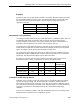
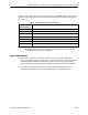
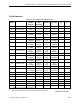
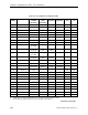
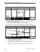
Table Of Contents
- Table of Contents
- How To Use This Manual
- Chapter 1—Hardware
- Chapter 2—Applications for ATEC— Base VAV
- Chapter 3—Applications for ATEC—VAV with Reheat
- Chapter Overview
- Introduction
- Application 2500: VAV Cooling Only
- Application 2501: VAV Cooling or Heating
- Application 2522: VAV with Electric Reheat or Baseboard Radiation
- Application 2523: VAV with Hot Water Reheat (only one reheat valve)
- Application 2524: VAV Series Fan Powered with One Stage of Electric Reheat
- Application 2526: VAV Parallel Fan Powered with One Stage of Electric Reheat
- Application 2473: Slave Mode
- Chapter 4—Point Database
- Chapter 5—Troubleshooting
- Glossary
- Index

Chapter 3—Applications for ATEC—VAV with Reheat
3-68 Siemens Building Technologies, Inc.
ROOM TEMPERATURE
CONTROL SCHEDULE
HEAT ON 100%
OF TIME
HEAT OFF
CLG FLOW MAX
COOLING *1
SET POINT
HEATING *1
SET POINT
COLDER WARMER
HEAT COOL
HTG FLOW MAX=
HTG FLOW MIN=
CLG FLOW MIN=
TEC2526CSR1
*2
*3
*4
*2
FAN OPERATION - DAY ON
FAN OPERATION - NIGHT ON
OFF
OFF
1. See Sequence of Operation, Control Temperature Setpoints.
2. See Sequence of Operation, Heating/Cooling Switchover.
3. When temperature is near the setpoint, heat is cycled on and off according to the size of the demand. This allows it to
be controlled proportionally rather than with deadbands.
4. The airflow is shown at minimum flow throughout the entire heating mode (default setting). The airflow can optionally
operate parallel (Figure 3-22), sequenced, or overlapping with the heat. See Sequencing Logic.
Figure 3-21. Application 2526 Control Schedule with Minimum Airflow during Heating (default).
ROOM TEMPERATURE
CONTROL SCHEDULE
HEAT ON 100%
OF TIME
HEAT OFF
CLG FLOW MAX
CLG FLOW MIN
COOLING *1
SET POINT
HEATING *1
SET POINT
COLDER WARMER
HEAT COOL
*2
*3
*4
*2
HTG FLOW MIN
HTG FLOW MAX
TEC2526CSOR1
FAN OPERATION - DAY ON
FAN OPERATION - NIGHT ON
OFF
OFF
1. See Sequence of Operation, Control Temperature Setpoints.
2. See Sequence of Operation, Heating/Cooling Switchover.
3. When temperature is near the setpoint, heat is cycled on and off according to the size of the demand. This allows
it to be controlled proportionally rather than with deadbands.
4. The airflow is shown operating parallel with the electric reheat. The airflow can operate at minimum flow
throughout the entire heating mode (Figure 3-21) or sequenced or overlapping with the heat. See Sequencing
Logic.
Figure 3-22. Application 2526 Control Schedule with Damper Modulated during Heating.