
Operating Instructions
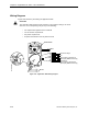
Table Of Contents
- Table of Contents
- How To Use This Manual
- Chapter 1—Hardware
- Chapter 2—Applications for ATEC— Base VAV
- Chapter 3—Applications for ATEC—VAV with Reheat
- Chapter Overview
- Introduction
- Application 2500: VAV Cooling Only
- Application 2501: VAV Cooling or Heating
- Application 2522: VAV with Electric Reheat or Baseboard Radiation
- Application 2523: VAV with Hot Water Reheat (only one reheat valve)
- Application 2524: VAV Series Fan Powered with One Stage of Electric Reheat
- Application 2526: VAV Parallel Fan Powered with One Stage of Electric Reheat
- Application 2473: Slave Mode
- Chapter 4—Point Database
- Chapter 5—Troubleshooting
- Glossary
- Index

Application 2526: VAV Parallel Fan Powered with One Stage of Electric Reheat
Siemens Building Technologies, Inc. 3-71
Night Mode Override Switch
If an override switch is present on the room temperature sensor and a value (in hours) other
than zero is entered into OVRD TIME (Point 20), pressing the override switch resets the
controller to day operational mode of the time period that is set in OVRD TIME. The status of
NGT OVRD (Point 21) changes to DAY. After the override time elapses, the controller returns
to night mode and NGT OVRD changes back to NIGHT.
It is only when the controller is in night mode that the override switch on the room sensor has
any effect on the controller.
Heating/Cooling Switchover
Based on Room Temperature (Internal Logic)
The heating/cooling switchover determines whether the controller is in heating or cooling
mode by monitoring the room temperature and the demand for heating and cooling (as
determined by the temperature control loops).
If the following conditions are met for the length of time set in SWITCH TIME (Point 86), the
controller switches from heating to cooling mode by setting HEAT.COOL (Point 5) to COOL:
• HTG LOOPOUT (Point 80) < SWITCH LIMIT (Point 85).
• CTL TEMP (Point 78) > CTL STPT (Point 92) by at least the value set in
SWITCH DBAND (Point 90).
• CTL TEMP > the appropriate cooling setpoint minus SWITCH DBAND.
If the following conditions are met for the length of time set in SWITCH TIME, the controller
switches from cooling to heating mode by setting HEAT.COOL to HEAT:
• CLG LOOPOUT (Point 79) < SWITCH LIMIT.
• CTL TEMP < CTL STPT by at least the value set in SWITCH DBAND.
• CTL TEMP < the appropriate heating setpoint plus SWITCH DBAND.
Based on Supply Air Temperature (External Control)
CAUTION:
The ATEC’s internal heating/cooling switchover mechanism is not affected by
the air temperature in the supply duct.
To change the value of HEAT.COOL (Point 5) based on the supply air temperature,
HEAT.COOL must be commanded through PPCL. This is required when the supply duct
delivers warm air for heat and cool air for cooling. In this case, the room-temperature-based
switchover must be disabled by commanding HEAT.COOL, and the heat/cool mode must be
based on the supply air temperature. When the supply air temperature is warm, the room is in
the heating mode. When it is cold, the room is in the cooling mode.