
Operating Instructions
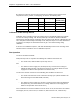
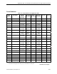
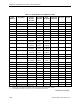
Table Of Contents
- Table of Contents
- How To Use This Manual
- Chapter 1—Hardware
- Chapter 2—Applications for ATEC— Base VAV
- Chapter 3—Applications for ATEC—VAV with Reheat
- Chapter Overview
- Introduction
- Application 2500: VAV Cooling Only
- Application 2501: VAV Cooling or Heating
- Application 2522: VAV with Electric Reheat or Baseboard Radiation
- Application 2523: VAV with Hot Water Reheat (only one reheat valve)
- Application 2524: VAV Series Fan Powered with One Stage of Electric Reheat
- Application 2526: VAV Parallel Fan Powered with One Stage of Electric Reheat
- Application 2473: Slave Mode
- Chapter 4—Point Database
- Chapter 5—Troubleshooting
- Glossary
- Index

Application 2526: VAV Parallel Fan Powered with One Stage of Electric Reheat
Siemens Building Technologies, Inc. 3-73
Electric Reheat
CAUTION:
Verify that the equipment is supplied with safeties by others to ensure that there is
airflow across the heating coils when they are to be energized.
CAUTION:
Do not set HTG FLOW MIN (Point 33) to 0 cfm (0 lps). A minimum airflow should
be provided across the heating coils, for ventilation and for dispersing heat.
The heating loop controls one stage of electric reheat to warm up the room. The electric
reheat is time-modulated using a duty cycle as shown in the following example. When the
controller is in cooling mode, the electric heat is off at all times.
Example
Assume the duty cycle (STAGE TIME, Point 89) is 10 minutes, REHEAT START (Point 22) is
0%, and REHEAT END (Point 23) is 100%. The following table shows the intervals during
which heat is on and off for various levels of demand from the heating loopout (HTG
LOOPOUT, Point 80).
HTG LOOPOUT Minutes ON Minutes OFF
40% 4 6
60% 6 4
100% 10 0
Sequencing Logic (Optional)
The settings of FLOW START (Point 16), FLOW END (Point 17), REHEAT START (Point 22),
and REHEAT END (Point 23) determine how the damper and reheat modulation are
sequenced while in heating mode. These points represent the values of HTG LOOPOUT
(Point 80) at which modulation of the damper and reheat begin and end.
The damper moves from minimum position to fully open as HTG LOOPOUT increases from
FLOW START to FLOW END. If FLOW START and FLOW END are both set to 0% (default
value), the damper stays at minimum position while in heating mode.
The cycle for the reheat ranges from always off to always on as HTG LOOPOUT increases
from REHEAT START to REHEAT END. Default values for these points are 0% and 100%
respectively. See Electric Reheat (page 3-73) for more information.