
Operating Instructions
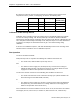
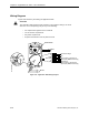
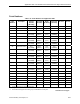
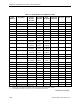
Table Of Contents
- Table of Contents
- How To Use This Manual
- Chapter 1—Hardware
- Chapter 2—Applications for ATEC— Base VAV
- Chapter 3—Applications for ATEC—VAV with Reheat
- Chapter Overview
- Introduction
- Application 2500: VAV Cooling Only
- Application 2501: VAV Cooling or Heating
- Application 2522: VAV with Electric Reheat or Baseboard Radiation
- Application 2523: VAV with Hot Water Reheat (only one reheat valve)
- Application 2524: VAV Series Fan Powered with One Stage of Electric Reheat
- Application 2526: VAV Parallel Fan Powered with One Stage of Electric Reheat
- Application 2473: Slave Mode
- Chapter 4—Point Database
- Chapter 5—Troubleshooting
- Glossary
- Index

Chapter 3—Applications for ATEC—VAV with Reheat
3-74 Siemens Building Technologies, Inc.
By varying the values of these start and end points, the damper and the reheat can be
sequenced in series, parallel, or overlapping, as shown in the following table:
Series Parallel Overlapping Minimum Flow
(Default Value)
FLOW START 0% 0% 0% 0%
FLOW END 50% 100% 75% 0%
REHEAT START 50% 0% 25% 0%
REHEAT END 100% 100% 100% 100%
Calibration of Air Velocity Sensor
Calibration of the controller’s internal air velocity sensor is periodically required to maintain
accurate air velocity readings. CAL SETUP (Point 95) is set with the desired calibration
option during controller startup. Depending upon the value of CAL SETUP, calibration may be
set to take place automatically or manually. If CAL AIR (Point 94) is set to YES, calibration is
in progress. The damper is commanded closed to get a zero airflow reading during
calibration.
At the end of a calibration sequence, CAL AIR automatically returns to NO. A setting of NO
indicates that the controller is not in a calibration sequence.
Fan Operation
The fan is controlled as follows:
FAN (Point 44) turns on only when the following two conditions have been met:
• The electric heat, HEAT STAGE 1 (Point 43), turns on.
-and-
• The airflow out of the supply duct, FLOW (Point 75), is less than the setting for
PARALLEL ON (Point 28). (This means that there is not enough airflow out of the
supply duct to allow for safe operation of the electric heat.)
The fan turns off when at least one of the following two conditions has been met:
• The electric heat has been off for at least one full duty cycle. (HEAT STAGE 1 has
been OFF longer than STAGE TIME, Point 89.)
-or-
• The airflow out of the supply duct, FLOW, is greater than the setting for PARALLEL
OFF (Point 30). (This means that there is enough airflow out of the supply duct to
allow for safe operation of the electric heat.)
If the conditions have not been satisfied to turn the fan on or off, the state of the fan remains
unchanged. (That is, if the fan is on, it remains on, while if the fan is off, it remains off.)