
Operating Instructions
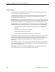
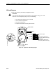
Table Of Contents
- Table of Contents
- How To Use This Manual
- Chapter 1—Hardware
- Chapter 2—Applications for ATEC— Base VAV
- Chapter 3—Applications for ATEC—VAV with Reheat
- Chapter Overview
- Introduction
- Application 2500: VAV Cooling Only
- Application 2501: VAV Cooling or Heating
- Application 2522: VAV with Electric Reheat or Baseboard Radiation
- Application 2523: VAV with Hot Water Reheat (only one reheat valve)
- Application 2524: VAV Series Fan Powered with One Stage of Electric Reheat
- Application 2526: VAV Parallel Fan Powered with One Stage of Electric Reheat
- Application 2473: Slave Mode
- Chapter 4—Point Database
- Chapter 5—Troubleshooting
- Glossary
- Index

Chapter 3—Applications for ATEC—VAV with Reheat
3-76 Siemens Building Technologies, Inc.
Wiring Diagram
Figure 3-23 shows the point wiring for Application 2526.
CAUTION:
The controller’s DOs control 24 Vac loads only. The maximum rating is 12 VA for
each DO. Use an interposing relay for any of the following:
• VA requirements higher than the maximum
• 110 or 220 Vac requirements
• DC power requirements
• Separate transformers used to power the load
Lo
Hi
24 Vac
FLN
90
90
4
5
TEC2526WDR2
654321
Electric Heat Stage 1
Fan
Spare AI (100K Thermistor) or
Spare DI (Dry contact closure only)
Wall Switch or
Spare AI (100K Thermistor) or
Spare DI (Dry contact closure only)
RTS
DO3
C
DO4
AI3
C
AI4
BST/FLN LED
Figure 3-23. Application 2526 Wiring Diagram.