
Operating Instructions
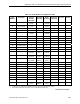
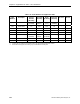
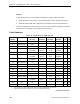
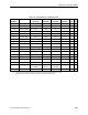

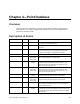
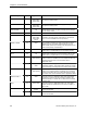
Table Of Contents
- Table of Contents
- How To Use This Manual
- Chapter 1—Hardware
- Chapter 2—Applications for ATEC— Base VAV
- Chapter 3—Applications for ATEC—VAV with Reheat
- Chapter Overview
- Introduction
- Application 2500: VAV Cooling Only
- Application 2501: VAV Cooling or Heating
- Application 2522: VAV with Electric Reheat or Baseboard Radiation
- Application 2523: VAV with Hot Water Reheat (only one reheat valve)
- Application 2524: VAV Series Fan Powered with One Stage of Electric Reheat
- Application 2526: VAV Parallel Fan Powered with One Stage of Electric Reheat
- Application 2473: Slave Mode
- Chapter 4—Point Database
- Chapter 5—Troubleshooting
- Glossary
- Index

Application 2473: Slave Mode
Siemens Building Technologies, Inc. 3-81
Application 2473: Slave Mode
Overview
Application 2473 is the slave mode application for the ATEC with Reheat (P/N 550-405).
Slave mode is the default application that comes up when power is first applied to the
controller. Slave mode provides no control. Its purpose is to allow the operator to perform
equipment checkout before a control application is put into effect and to set some basic
controller parameters (CTLR ADDRESS, APPLICATION, etc.). A controller in slave mode
can also be used as a point extension device by commanding spare I/O points from the field
panel.
Using Auxiliary Points
It is possible to have extra points available on an ATEC in addition to the ones used by the
current application that is running in the controller. If these extra points are to be controlled by
a field panel, then they must be unbundled at the field panel. See Table 3-14 (page 3-82) for
point database information.
Using the Controller as a Point Extension Device
If the controller is only used as a point extension device, with no control application in effect,
its application must be set to slave mode and points must be unbundled at the field panel. All
points must be controlled from the field panel in order to be used.
DO 3 and DO 4 may be used as separate DOs or as a pair to control a motor as shown in the
example.
NOTE: DO 1 and DO 2 are wired internally. They can only be used to rotate a shaft that
fits into the ATEC through 90° (or less).
NOTE: If using either a motor or DOs as auxiliary points, be sure to set MTR SETUP
(Point 58) to the correct value. See Table 3-13. If using a pair of DOs to control a
motor, then the DOs cannot be unbundled. Only MTR1 COMD (Point 48) and
MTR2 COMD (Point 52) can be unbundled to control the motors.
Table 3-13. Motor Enable/Reverse Values for MTR SETUP (Point 58).
Motor 1
Not Used Enabled
Enabled and
Reversed
Not Used
0
1
(default)
3
Enabled
4 5 7
Motor 2
Enabled and
Reversed
12 13 15