
Operating Instructions
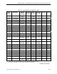
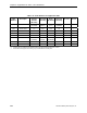

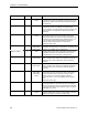
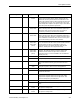
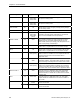
Table Of Contents
- Table of Contents
- How To Use This Manual
- Chapter 1—Hardware
- Chapter 2—Applications for ATEC— Base VAV
- Chapter 3—Applications for ATEC—VAV with Reheat
- Chapter Overview
- Introduction
- Application 2500: VAV Cooling Only
- Application 2501: VAV Cooling or Heating
- Application 2522: VAV with Electric Reheat or Baseboard Radiation
- Application 2523: VAV with Hot Water Reheat (only one reheat valve)
- Application 2524: VAV Series Fan Powered with One Stage of Electric Reheat
- Application 2526: VAV Parallel Fan Powered with One Stage of Electric Reheat
- Application 2473: Slave Mode
- Chapter 4—Point Database
- Chapter 5—Troubleshooting
- Glossary
- Index

Chapter 4—Point Database
4-2 Siemens Building Technologies, Inc.
Descriptor Address
Application Description
RM STPT MAX
12 All except slave
modes
The maximum temperature setpoint in degrees that the
controller can use from the setpoint dial. This overrides any
temperature setpoint from the setpoint dial that falls above
this maximum.
RM STPT DIAL
13 All The temperature setpoint in degrees from the room
temperature sensor (not available on all temperature
sensor models). This setpoint will be used for control in day
mode (heating or cooling) when enabled by STPT DIAL
(Point 14).
STPT DIAL
14 All except slave
modes
YES indicates that there is a room setpoint dial on the
room temperature sensor and it should be used as the
temperature setpoint for control in day/occupied mode. NO
indicates that the appropriate preset setpoint (Point 6, 7, 8,
9, or 10) will be used as the temperature setpoint for
control in day/occupied heating or cooling mode.
Valid input: YES or NO.
AI 3
15 2473, 2500,
2522, 2523,
2524, 2526
Actual reading from a 100K Ω thermistor connected to the
controller's Al 3 input. When a thermistor is connected at Al
3, DI 3 is not available. See DI 3 (Point 25).
SUPPLY TEMP
15 2501
Actual reading from a 100K Ω thermistor connected to the
controller's Al 3 input. The controller uses this value to
determine whether it is in heating or cooling mode.
FLOW START
16 2522, 2523,
2524, 2526
Determines how the damper modulation will be sequenced
while in heating mode. When HTG LOOPOUT (Point 80) is
above this value, then FLOW STPT (Point 93) starts to
increase.
FLOW END
17 2522, 2523,
2524, 2526
Determines how the damper modulation will be sequenced
while in heating mode. When HTG LOOPOUT (Point 80) is
below this value, then FLOW STPT (Point 93) starts to
decrease.
WALL SWITCH
18 2500, 2501,
2522, 2523,
2524, 2526,
(2473)
YES indicates that the controller is to monitor the status of
a wall switch that is connected to AI 4/DI 4. NO indicates
that the controller will not monitor the status of a wall
switch, even if one is connected. When a switch is
connected at DI 4, AI 4 is not available. See AI 4 (Point
40).
Valid input: YES or NO.
DI OVRD SW
19 All Actual indication of the status of the override switch (not
physically available on all temperature sensor models) at
the room temperature sensor. ON indicates that the switch
is being pressed. OFF indicates that the switch is released.
Valid input: ON or OFF.
OVRD TIME
20 All except slave
modes
The amount of time in hours that the controller will operate
in day/occupied mode when the override switch is pressed
while the controller is in night/unoccupied mode.