
Operating Instructions
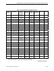
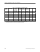
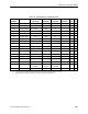
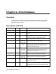
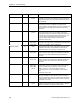
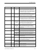
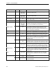
Table Of Contents
- Table of Contents
- How To Use This Manual
- Chapter 1—Hardware
- Chapter 2—Applications for ATEC— Base VAV
- Chapter 3—Applications for ATEC—VAV with Reheat
- Chapter Overview
- Introduction
- Application 2500: VAV Cooling Only
- Application 2501: VAV Cooling or Heating
- Application 2522: VAV with Electric Reheat or Baseboard Radiation
- Application 2523: VAV with Hot Water Reheat (only one reheat valve)
- Application 2524: VAV Series Fan Powered with One Stage of Electric Reheat
- Application 2526: VAV Parallel Fan Powered with One Stage of Electric Reheat
- Application 2473: Slave Mode
- Chapter 4—Point Database
- Chapter 5—Troubleshooting
- Glossary
- Index

Description of Points
Siemens Building Technologies, Inc. 4-3
Descriptor Address
Application Description
NGT OVRD
21 All except slave
modes
Indicates the mode that the controller is operating in with
respect to the override switch. NIGHT indicates that the
switch has not been pressed and the override timer is not
active. DAY indicates that the switch has been pressed and
the override timer is active. The controller then uses a day
mode temperature setpoint. This point is only in effect when
DAY.NGT (Point 29) indicates night mode.
REHEAT START
22 2522, 2523,
2524, 2526
Determines how the reheat modulation will be sequenced
while in heating mode. When HTG LOOPOUT (Point 80) is
above this value, then the reheat cycles on and off (or
remains on) according to the size of the demand.
REHEAT END
23 2522, 2523,
2524, 2526
Determines how the reheat modulation will be sequenced
while in heating mode. When HTG LOOPOUT (Point 80) is
at or above this value, reheat is on 100% of the time. When
HTG LOOPOUT is below this value, then the reheat cycles
on and off according to the size of the demand.
DI 4
24 2500, 2501,
2522, 2523,
2524, 2526,
(2473)
Actual status of a contact connected to the controller at
DI 4. ON indicates that the contact is closed; OFF indicates
that the contact is open. If a wall switch is used, it is
connected to DI 4. See WALL SWITCH (Point 18) and
SUPPLY TEMP (Point 15 for Application 2501).
DI 3
25 2500, 2501,
2522, 2523,
2524, 2526,
(2473)
Actual status of a contact connected to the controller at
Al 3/DI 3. ON indicates that the contact is closed; OFF
indicates that the contact is open. When a contact is
connected at DI 3, Al 3 is not available. See AI 3/SUPPLY
TEMP (Point 15).
SERIES ON
26 2524 When flow rises above this value, the series fan turns ON.
2526 This point is present, but not used in this application.
SERIES OFF
27 2524 When flow drops below this value and reheat has been
OFF for at least one full duty cycle, the series fan turns
OFF.
2526 This point is present, but not used in this application.
PARALLEL ON
28 2524 This point is present, but not used in this application.
2526 When flow drops below this value and reheat is ON, the
parallel fan turns ON.
DAY.NGT
29 All Indicates the mode in which the controller is operating. Day
temperature setpoints will be used in day mode. Night
temperature setpoints will be used in night mode. This
point is normally set by the field panel.
PARALLEL OFF
30 2524 This point is present, but not used in this application.
2526 When flow rises above this value, the parallel fan turns
OFF.
CLG FLOW MIN
31 All except slave
modes
The minimum amount of air in cfm (lps) to be supplied to
the space in cooling mode
CLG FLOW MAX
32 All except slave
modes
The maximum amount of air in cfm (lps) to be supplied to
the space in cooling mode. .