
Operating Instructions
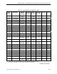
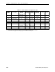
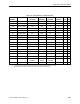
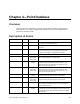
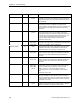
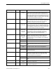
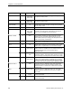
Table Of Contents
- Table of Contents
- How To Use This Manual
- Chapter 1—Hardware
- Chapter 2—Applications for ATEC— Base VAV
- Chapter 3—Applications for ATEC—VAV with Reheat
- Chapter Overview
- Introduction
- Application 2500: VAV Cooling Only
- Application 2501: VAV Cooling or Heating
- Application 2522: VAV with Electric Reheat or Baseboard Radiation
- Application 2523: VAV with Hot Water Reheat (only one reheat valve)
- Application 2524: VAV Series Fan Powered with One Stage of Electric Reheat
- Application 2526: VAV Parallel Fan Powered with One Stage of Electric Reheat
- Application 2473: Slave Mode
- Chapter 4—Point Database
- Chapter 5—Troubleshooting
- Glossary
- Index

Chapter 4—Point Database
4-4 Siemens Building Technologies, Inc.
Descriptor Address
Application Description
HTG FLOW MIN
33 2501, 2521,
2522, 2523,
2524, 2526
The minimum amount of air in cfm (lps) to be supplied to
the space in heating mode.
HTG FLOW MAX
34 2501, 2521,
2522, 2523,
2524, 2526
The maximum amount of air in cfm (lps) to be supplied to
the space in heating mode.
AIR VOLUME
35 All Actual amount of air in cfm (lps) currently passing through
the air velocity sensor.
FLOW COEFF
36 All Calibration factor for the airflow sensor.
AI 4
40 2500, 2501,
2522, 2523,
2524, 2526,
(2473)
Actual reading from a 100K Ω thermistor connected to the
controller's Al 4 input. When a thermistor is connected at
Al 4, DI 4 is not available. See DI 4 (Point 24).
SUPPLY TEMP
40 2521 The controller compares the value of this point to COOL
TEMP (Point 61) and HEAT TEMP (Point 62) and sets
HEAT.COOL (Point 5) accordingly. The field panel sets the
value of this point by commanding it.
DO 1
41 All Digital output 1 controls a 24 Vac load with an ON or OFF
status. DO 1 is coupled with DO 2 to control the damper.
DO 2
42 All Digital output 2 controls a 24 Vac load with an ON or OFF
status. DO 2 is coupled with DO 1 to control the damper.
DO 3
43 2500, 2501,
2523, (2473)
Digital output 3 controls a 24 Vac load with an ON or OFF
status. If Motor 2 is enabled, DO 3 is coupled with DO 4 to
control an actuator such as the hot-water valve in
Application 2523.
HEAT STAGE 1
43 2522, 2524,
2526
This point is DO 3 in applications with electric reheat or
baseboard radiation. This digital output controls the contact
for the first stage of heating and has a status of ON or OFF.
DO 4
44 2500, 2501,
2523, (2473)
Digital output 4 controls a 24 Vac load with an ON or OFF
status. If the Autozero Module is enabled, DO 4 controls it.
If Motor 2 is enabled, DO 4 is coupled with DO 3 to control
an actuator such as the hot-water valve in Application 2523.
HEAT STAGE 2
44 2522 This point is DO 4 in Application 2522. This digital output
controls the contact for the second stage of heating, the
Autozero Module, or another 24 Vac load and has a status
of ON or OFF.
FAN
44 2524, 2526 This point is DO 4 in applications with a fan. This digital
output controls the contact for the fan and has a status of
ON or OFF.
DMPR COMD
48 All except slave
modes
The value to which the damper motor is commanded in
percent of full travel.
MTR1 COMD
48 (2473), (2486) The value to which the Motor 1 actuator is commanded in
percent of full travel.