
Operating Instructions

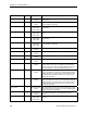
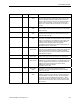
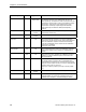
Table Of Contents
- Table of Contents
- How To Use This Manual
- Chapter 1—Hardware
- Chapter 2—Applications for ATEC— Base VAV
- Chapter 3—Applications for ATEC—VAV with Reheat
- Chapter Overview
- Introduction
- Application 2500: VAV Cooling Only
- Application 2501: VAV Cooling or Heating
- Application 2522: VAV with Electric Reheat or Baseboard Radiation
- Application 2523: VAV with Hot Water Reheat (only one reheat valve)
- Application 2524: VAV Series Fan Powered with One Stage of Electric Reheat
- Application 2526: VAV Parallel Fan Powered with One Stage of Electric Reheat
- Application 2473: Slave Mode
- Chapter 4—Point Database
- Chapter 5—Troubleshooting
- Glossary
- Index

Description of Points
Siemens Building Technologies, Inc. 4-5
Descriptor Address
Application Description
DMPR POS
49 All except slave
modes
The current position of the damper motor in percent of full
travel. This value is calculated based on motor run time.
See MTR1 TIMING (Point 51).
MTR1 POS
49 (2473), (2486) The current position of Motor 1 in percent of full travel. This
value is calculated based on motor run time. See MTR1
TIMING (Point 51).
MTR1 TIMING
51 All The time required for the Motor 1 (damper) actuator to
travel from full closed to the full open position.
MTR2 COMD
52 2500, 2501,
(2473)
The value to which the Motor 2 actuator is commanded in
percent of full travel (for use as an auxiliary slave point).
VLV COMD
52 2523 The value to which the hot-water valve actuator is
commanded in percent of full travel
MTR2 POS
53 2500, 2501,
(2473)
The current position of the Motor 2 actuator in percent of
full travel (for use as an auxiliary slave point). This value is
calculated based on motor run time. See MTR2 TIMING
(Point 55).
VLV POS
53 2523 The current position of the hot-water valve in percent of full
travel. This value is calculated based on motor run time.
See MTR2 TIMING (Point 55).
MTR2 TIMING
55 2500, 2501,
2523, (2473)
The time required for the Motor 2 actuator to travel from full
closed to the full open position.
DMPR ROT ANG
56 All except slave
modes
The number of degrees the damper is free to travel.
DPR1 ROT ANG
56 (2473), (2486) The number of degrees Damper 1 is free to travel.
DPR2 ROT ANG
57 (2473) The number of degrees Damper 2 is free to travel.
MTR SETUP
58 All The configuration setup code for Motors 1 and 2. This
enables the motors individually and sets each motor to be
either direct or reverse acting.
Note: When a motor is enabled, its associated DOs are
enabled.
DO DIR.REV
59 All The configuration setup code for DOs. Allows the DOs to
be direct or reverse acting (enabled equals energized or
enabled equals de-energized).
EHEAT FLOW
60 2522 The flow required before the electric heat will be enabled.
COOL TEMP
61 2501, 2521 The discharge air temperature where the controller will
switch from heating to cooling mode. Used only in
applications with SUPPLY TEMP (Point 15 or Point 40).
HEAT TEMP
62 2501, 2521 The discharge air temperature where the controller will
switch from cooling to heating mode. Used only in
applications with SUPPLY TEMP (Point 15 or Point 40).
CLG P GAIN
63 All except slave
modes
The proportional gain value for the cooling temperature
control loop.
CLG l GAIN
64 All except slave
modes
The integral gain value for the cooling temperature control
loop.