
Operating Instructions

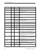
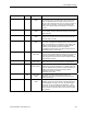
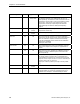
Table Of Contents
- Table of Contents
- How To Use This Manual
- Chapter 1—Hardware
- Chapter 2—Applications for ATEC— Base VAV
- Chapter 3—Applications for ATEC—VAV with Reheat
- Chapter Overview
- Introduction
- Application 2500: VAV Cooling Only
- Application 2501: VAV Cooling or Heating
- Application 2522: VAV with Electric Reheat or Baseboard Radiation
- Application 2523: VAV with Hot Water Reheat (only one reheat valve)
- Application 2524: VAV Series Fan Powered with One Stage of Electric Reheat
- Application 2526: VAV Parallel Fan Powered with One Stage of Electric Reheat
- Application 2473: Slave Mode
- Chapter 4—Point Database
- Chapter 5—Troubleshooting
- Glossary
- Index

Description of Points
Siemens Building Technologies, Inc. 4-7
Descriptor Address
Application Description
AVG HEAT OUT
81 2522, 2524,
2526
This point is used to determine what stages of electric heat
are used for a given loop output value. The ranges for the
value are determined by the number of stages used: 0 to
100 for 1 stage of electric heat, and 0 to 200 for 2 stages of
electric heat. For example, a value of 150 indicates that
Stage 1 is on 100% of the time and Stage 2 is on 50% of
the time.
STAGE MAX
82 2022, 2024,
2026
The value, in percent, which the heating loop must exceed
for the electric heat to be ON for the full duty cycle (STAGE
TIME, Point 89).
STAGE MIN
83 2522, 2524,
2526
The value, in percent, which the heating loop must go
below for the electric heat to be OFF for the full duty cycle
(STAGE TIME, Point 89).
DMPR STATUS
84 2500, 2501,
2522
This point is used only when CAL MODULE (Point 87) is
set to YES. It readjusts the damper position if the command
value is not equal to the actual position of the damper. CAL
indicates that the damper is operating normally. RECAL
indicates that the damper position was adjusted
(recalibrated) by 25% because the desired airflow was not
obtainable under its current status.
SWITCH LIMIT
85 2522, 2523,
2524, 2526
The active temperature control loop output must be less
than this value to switch between cooling mode and heating
mode. Actual switchover depends on SWITCH DBAND
(Point 90) being exceeded and is subject to SWITCH TIME
(Point 86) being expired.
SWITCH TIME
86 2522, 2523,
2524, 2526
The time, in minutes, before the heat/cool mode can
change over when the other parameters are appropriate.
CAL MODULE
87 2500, 2501,
2522, (2473)
YES indicates that the Autozero Module is enabled to
calibrate the air velocity transducer. The damper will not be
used for calibration. NO indicates that Autozero Module is
disabled and that the air velocity transducer will be
calibrated by closing the damper.
Valid input: YES or NO.
STAGE COUNT
88 2522, 2524,
2526
The number of electric heating stages used by the
application. DOs associated with unused stages may be
used as spare DOs.
STAGE TIME
89 2522, 2524,
2526
The cycle time in minutes for the electric reheat stages. For
example, if (a) there are two stages of electric heat (that is,
STAGE COUNT, Point 88, is set to 2), (b) STAGE TIME =
10 minutes, and (c) AVG HEAT OUT (Point 81) = 150%,
then Stage 1 is ON for 10 minutes (100% of the time), and
Stage 2 is ON for 5 minutes (50% of 10 minutes) and OFF
for 5 minutes.