
Operating Instructions

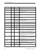
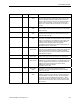
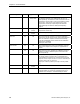
Table Of Contents
- Table of Contents
- How To Use This Manual
- Chapter 1—Hardware
- Chapter 2—Applications for ATEC— Base VAV
- Chapter 3—Applications for ATEC—VAV with Reheat
- Chapter Overview
- Introduction
- Application 2500: VAV Cooling Only
- Application 2501: VAV Cooling or Heating
- Application 2522: VAV with Electric Reheat or Baseboard Radiation
- Application 2523: VAV with Hot Water Reheat (only one reheat valve)
- Application 2524: VAV Series Fan Powered with One Stage of Electric Reheat
- Application 2526: VAV Parallel Fan Powered with One Stage of Electric Reheat
- Application 2473: Slave Mode
- Chapter 4—Point Database
- Chapter 5—Troubleshooting
- Glossary
- Index

Chapter 4—Point Database
4-8 Siemens Building Technologies, Inc.
Descriptor Address
Application Description
SWITCH DBAND
90 2522, 2523,
2524, 2526
The temperature range in degrees which is compared to
the difference between CTL TEMP (Point 78) and CTL
STPT (Point 92). The difference must exceed this value for
temperature control mode to change over between heating
and cooling. Changeover is also subject to the active
temperature control loop output being below SWITCH
LIMIT (Point 85) and SWITCH TIME (Point 86) being
expired.
CTL STPT
92 All except slave
modes
The actual setpoint value being used as input for the active
temperature control loop.
FLOW STPT
93 All except slave
modes
The currently active setpoint of the flow control loop.
CAL AIR
94 All YES commands the controller to go through calibration
sequence for the air velocity sensor. YES is also displayed
when the calibration sequence is started automatically.
CAL AIR automatically returns to NO after the calibration
sequence is completed.
Valid input: YES or NO.
CAL SETUP
95 All The configuration setup code for the calibration sequence
options. See Chapter 2 and Chapter 3—Applications for
details.
CAL TIMER
96 All Time interval, in hours, between the calibration sequence
initiations if a timed calibration option is selected in CAL
SETUP (Point 95).
DUCT AREA
97 All Area, in square feet (square meters), of the duct where the
air velocity sensor is located. This is a calculated value
(calculated by the field panel or computer being used) that
depends on duct shape and size. It is used in calculating all
points in units of cfm, cf, lps and L.
Valid input: 0.025 ft
2
(0.002 m
2
) through 6.375 ft
2
(0.5923
m
2
).
LOOP TIME
98 All except slave
modes
The time, in seconds, between control loop calculations.
ERROR STATUS
99 All The status code indicating any errors detected during
controller power up. A status of 0 indicates there are no
problems. See Chapter 5—Troubleshooting for details.