
Operating Instructions

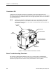
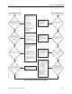
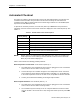
Table Of Contents
- Table of Contents
- How To Use This Manual
- Chapter 1—Hardware
- Chapter 2—Applications for ATEC— Base VAV
- Chapter 3—Applications for ATEC—VAV with Reheat
- Chapter Overview
- Introduction
- Application 2500: VAV Cooling Only
- Application 2501: VAV Cooling or Heating
- Application 2522: VAV with Electric Reheat or Baseboard Radiation
- Application 2523: VAV with Hot Water Reheat (only one reheat valve)
- Application 2524: VAV Series Fan Powered with One Stage of Electric Reheat
- Application 2526: VAV Parallel Fan Powered with One Stage of Electric Reheat
- Application 2473: Slave Mode
- Chapter 4—Point Database
- Chapter 5—Troubleshooting
- Glossary
- Index

Chapter 5—Troubleshooting
5-4 Siemens Building Technologies, Inc.
Controller LED
To determine if the controller is powered up and working, verify that the Basic Sanity Test
(BST)/Floor Level Network (FLN) Light Emitting Diode (LED) is flashing ON/OFF once per second
or is steadily illuminated. The BST/FLN LED is near the upper right-hand corner of the controller’s
front surface (Figure 5-1).
NOTE: A blinking LED indicates communication over the FLN. A steadily lit LED indicates
stand-alone operation. The LED blinks for two minutes after power-up or loss of
communication over the FLN. If there is still no communication after two minutes, the
LED becomes steadily lit.
EHC
Lo
Hi
24 VAC
Air Velocity
Sensor
Room Temperature
Sensor Connection
I/O
Connections
FLN Connection
Power
Connection
BST/FLN LED
TEC0436R1
Figure 5-1. Location of LED and Connections on ATEC.
Basic Troubleshooting Flowchart
Use the Basic Troubleshooting Flowchart, Figure 5-2, as a quick guide for troubleshooting
common controller problems. Use it to find the paragraphs and procedures in this section that
describe the symptom and the corrective action you should take to solve a problem.