
Operating Instructions
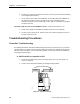
Table Of Contents
- Table of Contents
- How To Use This Manual
- Chapter 1—Hardware
- Chapter 2—Applications for ATEC— Base VAV
- Chapter 3—Applications for ATEC—VAV with Reheat
- Chapter Overview
- Introduction
- Application 2500: VAV Cooling Only
- Application 2501: VAV Cooling or Heating
- Application 2522: VAV with Electric Reheat or Baseboard Radiation
- Application 2523: VAV with Hot Water Reheat (only one reheat valve)
- Application 2524: VAV Series Fan Powered with One Stage of Electric Reheat
- Application 2526: VAV Parallel Fan Powered with One Stage of Electric Reheat
- Application 2473: Slave Mode
- Chapter 4—Point Database
- Chapter 5—Troubleshooting
- Glossary
- Index

Automated Checkout
Siemens Building Technologies, Inc. 5-7
3. Connect directly to the controller through the room temperature sensor connection
on the ATEC and check whether communication is possible. If so, the problem lies
in the room temperature sensor or its cable. If not, the problem is with the controller.
4. Contact your local Siemens Building Technologies representative.
Air velocity sensor failed—CHK STATUS (Point 3) = 4
1. The sensor tubing may be blocked, leaking, or disconnected. Check for pinched,
disconnected, or cracked sensor tubing. Correct as needed.
2. The tubing connections for the air velocity sensor may be reversed. Repipe if HI and
LO connections are incorrect.
3. The sensor or the ATEC may be faulty. See “Air Velocity Sensor Troubleshooting”
on page 5-15.
Controller could not reach CLG FLOW MIN or below—CHK STATUS (Point 3) = 8
1. The actuator may be loose on the shaft. Check that the setscrew is fully tightened
against the damper shaft. Follow these torque guidelines:
• 70 ± 5 inch pounds—solid metal
• 37 ± 2 inch pounds—plastic, graphite, composite, or hollow metal (Hollow metal
shafts require an insert to prevent shaft damage.)
2. The tubing for the air velocity sensor may be pinched, disconnected, or cracked.
Check the tubing and correct as needed.
3. The tubing connections for the air velocity sensor may be reversed. Repipe if HI and
LO connections are incorrect.
4. Box sizing information may be incorrect. Check the values of the following points
and correct as needed:
• DUCT AREA (Point 97)
• FLOW COEFF (Point 36)
• CLG FLOW MIN (Point 31)
• CLG FLOW MAX (Point 32)
5. Motor setup information may be incorrect. Check the values of the following points
and correct as needed:
• MTR SETUP (Point 58; see Table 5-2 on page 5-17)
• MTR1 TIMING (Point 51)
• DMPR ROT ANG (Point 56)