
Operating Instructions
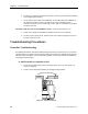
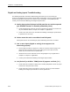
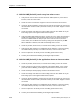
Table Of Contents
- Table of Contents
- How To Use This Manual
- Chapter 1—Hardware
- Chapter 2—Applications for ATEC— Base VAV
- Chapter 3—Applications for ATEC—VAV with Reheat
- Chapter Overview
- Introduction
- Application 2500: VAV Cooling Only
- Application 2501: VAV Cooling or Heating
- Application 2522: VAV with Electric Reheat or Baseboard Radiation
- Application 2523: VAV with Hot Water Reheat (only one reheat valve)
- Application 2524: VAV Series Fan Powered with One Stage of Electric Reheat
- Application 2526: VAV Parallel Fan Powered with One Stage of Electric Reheat
- Application 2473: Slave Mode
- Chapter 4—Point Database
- Chapter 5—Troubleshooting
- Glossary
- Index

Chapter 5—Troubleshooting
5-8 Siemens Building Technologies, Inc.
6. The box may not have been balanced correctly. Contact your local Siemens Building
Technologies Representative.
7. The air velocity sensor may need calibration. Set CAL AIR (Point 94) to YES to run
the calibration sequence. When CAL AIR returns to NO, indicating that the
sequence is finished, run the checkout procedure again to see whether the problem
has been corrected.
Controller could not reach CLG FLOW MAX or above—CHK STATUS (Point 3) = 16
1. Check for the problems described immediately above for CLG FLOW MIN.
2. The box may be starved for air, either because the central air-handling unit is off or
because of low duct static.
Troubleshooting Procedures
Controller Troubleshooting
The following information describes troubleshooting procedures you should use if you encounter
a problem with the controller. Find the symptom that best describes the problem and perform the
corrective action that follows. For any unresolved problem, contact your local Siemens Building
Technologies representative.
A. BST/FLN LED on controller is OFF.
1. Check the incoming 24 Vac power to controller (19.2–27.6 Vac). See Figure 5-3.
Correct as required.
2. Contact your local Siemens Building Technologies representative.
TEC0467R1
C H E
EARTH GND
24 VAC HOT
COMMON
CONTROLLER POWER WIRING
Figure 5-3. ATEC Power Wiring.