
Operating Instructions
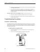
Table Of Contents
- Table of Contents
- How To Use This Manual
- Chapter 1—Hardware
- Chapter 2—Applications for ATEC— Base VAV
- Chapter 3—Applications for ATEC—VAV with Reheat
- Chapter Overview
- Introduction
- Application 2500: VAV Cooling Only
- Application 2501: VAV Cooling or Heating
- Application 2522: VAV with Electric Reheat or Baseboard Radiation
- Application 2523: VAV with Hot Water Reheat (only one reheat valve)
- Application 2524: VAV Series Fan Powered with One Stage of Electric Reheat
- Application 2526: VAV Parallel Fan Powered with One Stage of Electric Reheat
- Application 2473: Slave Mode
- Chapter 4—Point Database
- Chapter 5—Troubleshooting
- Glossary
- Index

Troubleshooting Procedures
Siemens Building Technologies, Inc. 5-9
B. BST/FLN LED on controller does not flash but instead remains lit
when connected to an FLN trunk. Communication with controller via
Datamate is possible.
NOTE: The BST/FLN LED flashes for two minutes after power-up or disconnection
from the FLN. If there is still no communication after two minutes, the LED
turns on steadily. Thus, it is necessary to wait for two minutes to determine
whether the LED will continue flashing or not.
1. See FLN Trunk Connections Check on page 5-22. Check the FLN trunk wiring for
proper connection and polarity.
2. Check that a point exists in the field panel database for the FLN device. Correct as
required.
3. Check that the address for the ATEC in the field panel shows the correct FLN trunk
(1 to 3) and drop (addresses 0 to 98 are valid; 0 to 31 are typically used). Change if
necessary.
4. Check that CTRL ADDRESS (Point 1) in the ATEC matches its drop number in the
field panel. Change if necessary.
5. Contact your local Siemens Building Technologies representative.
C. Cannot communicate with the controller through the port on the
room temperature sensor.
1. Check the incoming 24 Vac power to controller (19.2 to 27.6 Vac). See Figure 5-3.
Correct as required.
2. The cable for the room temperature sensor may be unplugged or loose. Check both
ends to ensure that the cable is securely seated.
3. Connect directly to the controller through the room temperature sensor connection
on the ATEC and check whether communication is possible. If so, the problem lies
in the room temperature sensor or its cable. If not, the problem is with the controller.
4. Contact your local Siemens Building Technologies representative.
D. Communication with controller possible while connected to the
room temperature sensor, but unable to control setpoint via the dial.
1. Controller may be in night mode. Check the day/night wall switch for proper setting.
2. Check that the controller is set up to use the dial by ensuring that STPT DIAL (Point
14) is set to YES. Reset if necessary.
3. Check the settings for maximum and minimum values that the controller will accept
from the setpoint dial (RM STPT MIN, Point 11, and RM STPT MAX, Point 12).
Adjust as necessary.