
Operating Instructions
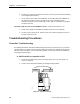
Table Of Contents
- Table of Contents
- How To Use This Manual
- Chapter 1—Hardware
- Chapter 2—Applications for ATEC— Base VAV
- Chapter 3—Applications for ATEC—VAV with Reheat
- Chapter Overview
- Introduction
- Application 2500: VAV Cooling Only
- Application 2501: VAV Cooling or Heating
- Application 2522: VAV with Electric Reheat or Baseboard Radiation
- Application 2523: VAV with Hot Water Reheat (only one reheat valve)
- Application 2524: VAV Series Fan Powered with One Stage of Electric Reheat
- Application 2526: VAV Parallel Fan Powered with One Stage of Electric Reheat
- Application 2473: Slave Mode
- Chapter 4—Point Database
- Chapter 5—Troubleshooting
- Glossary
- Index

Troubleshooting Procedures
Siemens Building Technologies, Inc. 5-11
4. If all equipment controllers on the FLN trunk are failed, contact your local Siemens
Building Technologies representative.
H. A value entered into the controller using Datamate immediately
changes back to its previous value.
1. The field panel may be updating the controller through the execution of PPCL code.
Evaluate the PPCL code to ensure proper operation. See APOGEE PPCL User
Manual (125-1896) for more information.
2. Disconnect the controller from the FLN trunk and check for proper operation. If the
value continues to revert to its previous value, the controller must be replaced.
3. Contact you local Siemens Building Technologies representative.
I. Upon recovery from a power loss to the controller, or recovery from
a communication loss with the field panel, a value entered into the
controller using Datamate immediately changes back to its previous
value.
The field panel is updating the controller with the initial value block (Scuinitvals). Update
the initial value block (Scuinitvals) at the field panel. See APOGEE Field Panel User's
Manual (125-3000) for more information.
J. Room temperature is too cold or too hot.
1. Adjust heating or cooling setpoint as appropriate.
2. If the controller is using a setpoint dial, ensure that STPT DIAL (Point 14) is set to
YES. Also check the settings for maximum and minimum values that the controller
will accept from the setpoint dial (RM STPT MIN, Point 11, and RM STPT MAX,
Point 12). Adjust as necessary.
3. Check the operation of the valve and/or damper actuator (page 5-23), the damper,
and the damper linkage. Repair or replace as necessary.
4. Check priority of points to see if any are overridden. Release as appropriate.
5. Contact your local Siemens Building Technologies representative.
K. Analog input points displayed at the field panel are not reading as
expected (pre-APOGEE firmware or manually unbundled points).
1. Improper slope/intercept value for the point may be entered in the field panel
database. Check the slope/intercept entries for the point and correct as needed. See
the point database tables in Chapter 2 or Chapter 3—Applications for slope/intercept
values.