
Operating Instructions
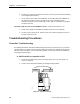
Table Of Contents
- Table of Contents
- How To Use This Manual
- Chapter 1—Hardware
- Chapter 2—Applications for ATEC— Base VAV
- Chapter 3—Applications for ATEC—VAV with Reheat
- Chapter Overview
- Introduction
- Application 2500: VAV Cooling Only
- Application 2501: VAV Cooling or Heating
- Application 2522: VAV with Electric Reheat or Baseboard Radiation
- Application 2523: VAV with Hot Water Reheat (only one reheat valve)
- Application 2524: VAV Series Fan Powered with One Stage of Electric Reheat
- Application 2526: VAV Parallel Fan Powered with One Stage of Electric Reheat
- Application 2473: Slave Mode
- Chapter 4—Point Database
- Chapter 5—Troubleshooting
- Glossary
- Index

Troubleshooting Procedures
Siemens Building Technologies, Inc. 5-13
D. Measured temperature is not the actual room temperature, or the
room temperature readings fluctuate.
1. The cable for the room temperature sensor may be unplugged or loose. Check both
ends to ensure that the cable is securely seated.
2. Check that the sensor is not exposed to direct sunlight and that there are no drafts
coming through the wall board, bricks, and so on. The sensor must not be located
where temperature changes are frequent (that is, near a window, an outside door, or
a diffuser) or near fluorescent light dimmers. Contact your local Siemens Building
Technologies representative if sensor relocation is necessary.
3. ROOM TEMP (Point 4) may be overridden. Check the priority of ROOM TEMP. If
the priority is displayed as OVRD, then release the point.
4. Contact your local Siemens Building Technologies representative if sensor or cable
replacement is necessary.
E. Adjusting the sensor setpoint dial has no effect on the value of
RM STPT DIAL (Point 13).
1. Check that the controller is set up to use the dial by ensuring that STPT DIAL (Point
14) is set to YES. Reset if necessary.
2. RM STPT DIAL (Point 13) may be overridden. Check the priority of RM STPT DIAL.
If the priority is displayed as OVRD, then release the point.
3. Check the settings for maximum and minimum values that the controller will accept
from the setpoint dial (RM STPT MIN, Point 11, and RM STPT MAX, Point 12).
Adjust as necessary.
4. The cable for the room temperature sensor may be unplugged or loose. Check
whether RM STPT DIAL (Point 13) appears as failed, (*F*). If so, check both ends
of the cable to ensure that it is securely seated.
5. Contact your local Siemens Building Technologies representative if sensor or cable
replacement is necessary.
F. AI 3 (Point 15) or SUPPLY TEMP (Point 15) appears as failed, (*F*).
1. Check cable from controller to supply-duct or auxiliary temperature sensor for proper
connection to AI 3 (terminals 4 and 5).
2. Check temperature sensor and replace if necessary. Contact your local Siemens
Building Technologies representative if sensor or cable replacement is necessary.