
Operating Instructions
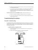
Table Of Contents
- Table of Contents
- How To Use This Manual
- Chapter 1—Hardware
- Chapter 2—Applications for ATEC— Base VAV
- Chapter 3—Applications for ATEC—VAV with Reheat
- Chapter Overview
- Introduction
- Application 2500: VAV Cooling Only
- Application 2501: VAV Cooling or Heating
- Application 2522: VAV with Electric Reheat or Baseboard Radiation
- Application 2523: VAV with Hot Water Reheat (only one reheat valve)
- Application 2524: VAV Series Fan Powered with One Stage of Electric Reheat
- Application 2526: VAV Parallel Fan Powered with One Stage of Electric Reheat
- Application 2473: Slave Mode
- Chapter 4—Point Database
- Chapter 5—Troubleshooting
- Glossary
- Index

Troubleshooting Procedures
Siemens Building Technologies, Inc. 5-15
Air Velocity Sensor Troubleshooting
The following information describes troubleshooting procedures you should use if you encounter
a problem with an air velocity sensor or with the controller's internal air velocity transducer
(differential pressure transducer). Find the symptom that best describes the problem and perform
the corrective action that follows. If the problem persists, contact your local Siemens Building
Technologies representative.
A. AIR VOLUME (Point 35) reads failed, (*F*).
1. Clean or replace the air velocity sensor (located in the duct).
2. If velocity is greater than 4000 fpm (20.32 m/sec) (not 4000 cfm), take corrective
action to decrease the velocity.
3. Check for pinched, disconnected, or cracked sensor tubing. Correct as needed.
4. Check the sensor connections. Repipe if HI and LO connections are reversed.
5. Verify that the correct value is entered for DUCT AREA (Point 97). If incorrect, enter
the correct value.
6. Contact your local Siemens Building Technologies representative.
B. AIR VOLUME (Point 35) reads a very high value.
1. Check for pinched, disconnected, or cracked sensor tubing. Correct as needed.
2. Check the sensor connections. Repipe if HI and LO connections are reversed.
3. If using an Autozero Module, check that the HI and LO connections are correct and
that the module is wired to DO 4 (terminals 2 and 3) on the ATEC. Repipe or rewire
as needed.
4. Verify that the correct value is entered for DUCT AREA (Point 97). If incorrect, enter
the correct value.
5. Recalibrate air velocity sensor by setting CAL AIR (Point 94) to YES. When
calibration is finished, CAL AIR automatically returns to NO.
6. Verify that the flow coefficient, as supplied by the air balancer, is entered correctly
for FLOW COEFF (Point 36). If the value is incorrect, enter the correct value.
7. Clean or replace the duct sensor and tubing.
8. Contact your local Siemens Building Technologies representative.