
Operating Instructions
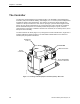
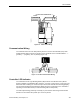
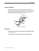
Table Of Contents
- Table of Contents
- How To Use This Manual
- Chapter 1—Hardware
- Chapter 2—Applications for ATEC— Base VAV
- Chapter 3—Applications for ATEC—VAV with Reheat
- Chapter Overview
- Introduction
- Application 2500: VAV Cooling Only
- Application 2501: VAV Cooling or Heating
- Application 2522: VAV with Electric Reheat or Baseboard Radiation
- Application 2523: VAV with Hot Water Reheat (only one reheat valve)
- Application 2524: VAV Series Fan Powered with One Stage of Electric Reheat
- Application 2526: VAV Parallel Fan Powered with One Stage of Electric Reheat
- Application 2473: Slave Mode
- Chapter 4—Point Database
- Chapter 5—Troubleshooting
- Glossary
- Index

The Controller
Siemens Building Technologies, Inc. 1-3
The ATEC with Reheat model (Figure 1-2) is designed to control terminal boxes, either single
duct or fan powered (series or parallel), with hot water reheat or up to two stages of electric
reheat. It includes Applications 2500, 2501, 2522, 2523, 2524, and 2526. It has removable
terminal blocks for FLN, I/O, and power terminations. An Autozero Module can be used with
this controller for Applications 2500, 2501, and 2522. An Autozero Module is required for
applications where continuous airflow is required for an area.
EHC
Lo
Hi
24 VAC
Air Velocity
Sensor
Room Temperature
Sensor Connection
I/O
Connections
FLN Connection
Power
Connection
BST/FLN LED
TEC0436R1
Figure 1-2. Actuating Terminal Equipment Controller (ATEC)—VAV with Reheat.
Digital Inputs
Both models of the controller have Digital Input (DI) 1. DI 1 is associated with the room-
temperature-sensor cable (specifically, the sensor's override switch) and is displayed on
screen as DI OVRD SW (Point 19). This DI cannot be wired is and not available for use as an
auxiliary point.
In addition to DI 1, the ATEC with Reheat has DI 3 (terminals 4 and 5) and DI 4 (terminals 5
and 6) These inputs are typically used to monitor the status of a dry contact such as a switch
or an auxiliary contact. DI 4 can be used with a wall switch that changes the controller from
day mode to night mode and back again. See Chapter 3—Applications for ATEC—VAV with
Reheat for more information.
NOTE: In all applications for the ATEC with Reheat, the inputs labeled "AI 3" and “AI 4”
on the controller can each be used either as a DI point or as an Analog Input (AI)
point, but neither can be used for both at the same time.