
Operating Instructions
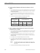
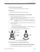
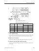
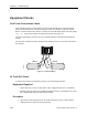
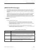
Table Of Contents
- Table of Contents
- How To Use This Manual
- Chapter 1—Hardware
- Chapter 2—Applications for ATEC— Base VAV
- Chapter 3—Applications for ATEC—VAV with Reheat
- Chapter Overview
- Introduction
- Application 2500: VAV Cooling Only
- Application 2501: VAV Cooling or Heating
- Application 2522: VAV with Electric Reheat or Baseboard Radiation
- Application 2523: VAV with Hot Water Reheat (only one reheat valve)
- Application 2524: VAV Series Fan Powered with One Stage of Electric Reheat
- Application 2526: VAV Parallel Fan Powered with One Stage of Electric Reheat
- Application 2473: Slave Mode
- Chapter 4—Point Database
- Chapter 5—Troubleshooting
- Glossary
- Index

Chapter 5—Troubleshooting
5-18 Siemens Building Technologies, Inc.
B. Actuator position displays as 100% open, but damper or valve is
closed.
1. For an externally wired actuator (the valve in Application 2523 or an actuator used in
slave mode for the ATEC with Reheat), verify proper wiring. See Table 5-3 and the
installation wiring diagram.
2. Try changing MTR SETUP (Point 58) to reverse the action of the actuator. See
Table 5-2. If this does not correct the problem, return MTR SETUP to its previous
value.
3. Contact your local Siemens Building Technologies representative.
Table 5-3. Actuator Terminal Block Codes.
Electronic Actuator
3-Point Floating Signal, Fail-
in-Place
Terminal Code/Wire Color
damper
(GDE131.1U or
GLB131.1P)
Violet (Y1)
clockwise
Red (G)
COM
Orange (Y2)
counterclockwise
valve
(SSB81U or SSC81U)
Y1
Extend
G
COM
Y2
Retract
C. Valve or damper position displays as 0% open, but flow remains
through the valve or damper.
1. For an externally wired actuator (the valve in Application 2523 or an actuator used in
slave mode for the ATEC with Reheat), verify proper wiring. See Table 5-3 and the
installation wiring diagram.
2. Try changing MTR SETUP (Point 58) to reverse the action of the actuator. See
Table 5-2 on page 5-17. If this does not correct the problem, return MTR SETUP to
its previous value.
3. For a damper, check for damper binding and correct as needed.
4. For a damper, confirm proper alignment of damper shaft in actuator bushing.
Damper shaft must not be off-center or sized improperly. See Figure 5-5 on
page 5-19.
NOTE: The damper actuator includes a 1/2-inch adapter insert ready to mount
on 1/2-inch shafts. For 3/8-inch shafts, a 3/8-inch insert is shipped in the
actuator box.
5. Contact your local Siemens Building Technologies representative.