
Operating Instructions
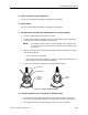
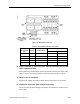
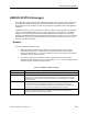
Table Of Contents
- Table of Contents
- How To Use This Manual
- Chapter 1—Hardware
- Chapter 2—Applications for ATEC— Base VAV
- Chapter 3—Applications for ATEC—VAV with Reheat
- Chapter Overview
- Introduction
- Application 2500: VAV Cooling Only
- Application 2501: VAV Cooling or Heating
- Application 2522: VAV with Electric Reheat or Baseboard Radiation
- Application 2523: VAV with Hot Water Reheat (only one reheat valve)
- Application 2524: VAV Series Fan Powered with One Stage of Electric Reheat
- Application 2526: VAV Parallel Fan Powered with One Stage of Electric Reheat
- Application 2473: Slave Mode
- Chapter 4—Point Database
- Chapter 5—Troubleshooting
- Glossary
- Index

Troubleshooting Procedures
Siemens Building Technologies, Inc. 5-21
Figure 5-6. Relay Module (540-147).
Table 5-4. Relay Module (540-147) Connections.
ATEC
Relay Module
Input Terminal
Pin
Relay
Number
Relay Module
Terminal Block
DO Screw Terminal
1 – COMMON – 2
2 K1 COM1, NO1, NC1
DO 3 1
3 K2 COM2, NO2, NC2
DO 4 3
4 K3 COM3, NO3, NC3
– –
5 K4 COM4, NO4, NC4
– –
B. Load controlled by relay turns OFF when it should be ON, and ON
when it should be OFF.
Rewire load being controlled to the proper relay module terminals. Use caution when
wiring, or contact your Siemens Building Technologies representative for service.
C. Relay never de-energizes.
Check that the cabling connecting controller board to relay module is not shorted.
D. Load never turns OFF (low voltage loads only).
Contact your local Siemens Building Technologies representative for replacement of
relay module.