
Operating Instructions
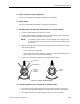
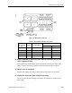
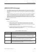
Table Of Contents
- Table of Contents
- How To Use This Manual
- Chapter 1—Hardware
- Chapter 2—Applications for ATEC— Base VAV
- Chapter 3—Applications for ATEC—VAV with Reheat
- Chapter Overview
- Introduction
- Application 2500: VAV Cooling Only
- Application 2501: VAV Cooling or Heating
- Application 2522: VAV with Electric Reheat or Baseboard Radiation
- Application 2523: VAV with Hot Water Reheat (only one reheat valve)
- Application 2524: VAV Series Fan Powered with One Stage of Electric Reheat
- Application 2526: VAV Parallel Fan Powered with One Stage of Electric Reheat
- Application 2473: Slave Mode
- Chapter 4—Point Database
- Chapter 5—Troubleshooting
- Glossary
- Index

Chapter 5—Troubleshooting
5-22 Siemens Building Technologies, Inc.
Equipment Checks
FLN Trunk Connections Check
If the controller connects to a field panel via a Floor Level Network (FLN), make sure that the
wiring is terminated properly at both the field panel and at the controller's FLN trunk terminal
blocks. The wires should not be shorted or loosely connected. Maintain proper FLN trunk polarity:
+ to +; − to −. Verify that the shields are properly terminated. See Figure 5-7.
If the FLN Trunk wiring is reversed, then the controller's BST/FLN LED will remain illuminated
steadily.
It is normal for the BST/FLN LED to be illuminated steadily if there is no FLN trunk connected to
the controller.
TEC0463R1
+
-
S
(SHIELD) (SHIELD)
(+)
(+)
(-)
(-)
Figure 5-7. FLN Trunk Wiring.
DI 3 and DI 4 Check
To check if DI 3 and DI 4 are functioning properly, use the following procedure.
Equipment Required
• Jumper wire (use a 3-inch (76-mm) piece of wire, stripped at both ends, or equivalent).
• Datamate (Base or Advanced) and IBM-compatible computer, or Handheld PC or Pocket
PC™ with Windows CE, plus communications cable.
Procedure
1. Plug into the communication port on the room temperature sensor. Scroll so that the
display shows DI 4 (Point 24) or DI 3 (Point 25).