
Operating Instructions
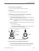
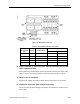
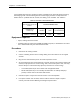
Table Of Contents
- Table of Contents
- How To Use This Manual
- Chapter 1—Hardware
- Chapter 2—Applications for ATEC— Base VAV
- Chapter 3—Applications for ATEC—VAV with Reheat
- Chapter Overview
- Introduction
- Application 2500: VAV Cooling Only
- Application 2501: VAV Cooling or Heating
- Application 2522: VAV with Electric Reheat or Baseboard Radiation
- Application 2523: VAV with Hot Water Reheat (only one reheat valve)
- Application 2524: VAV Series Fan Powered with One Stage of Electric Reheat
- Application 2526: VAV Parallel Fan Powered with One Stage of Electric Reheat
- Application 2473: Slave Mode
- Chapter 4—Point Database
- Chapter 5—Troubleshooting
- Glossary
- Index

Equipment Checks
Siemens Building Technologies, Inc. 5-23
2. Connect the jumper wire between the controller screw terminals 4 and 5 (labeled “AI 3”)
for the DI 3 point, or screw terminals 5 and 6 (labeled “AI 4”) for the DI 4 point. See
Figure 5-1 on page 5-4. Verify that the value of the point is ON, indicating a contact
closure.
3. Remove the jumper wire from one of the terminals. Verify that the value of the point is
OFF. If DI 3 and DI 4 do not toggle ON and OFF, then contact your local Siemens
Building Technologies representative.
Al 3 and AI 4 Check
Equipment Required
• Accurate thermometer (digital or analog)
• Datamate (Base or Advanced) and IBM-compatible computer, or Handheld PC or Pocket
PC™ with Windows CE, plus communications cable
Procedure
1. Plug into the communication port on the room temperature sensor.
2. Check the status of AI 3 or SUPPLY TEMP (Point 15), or AI 4 (Point 40).
3. If the point is failed (
*F*), check the cable that connects the temperature sensor to the
controller. Make sure that both ends are properly terminated. If a connection problem
cannot be found, contact your local Siemens Building Technologies representative for
possible sensor replacement.
4. If the point is not failed, use an accurate thermometer to measure the temperature.
Compare this value with the value for Point 15 or Point 40. If the values differ by more
than 5°F (2.8°C), contact your local Siemens Building Technologies representative for
sensor replacement.
5. If, after replacing the sensor, the values still differ by more than 5°F (2.8°C) (or if Point 15
or Point 40 still shows failed), contact your local Siemens Building Technologies
representative.
Actuator Check
The actuator receives power through the controller, which switches triacs at the actuator
terminations DO 1 through DO 4. DO 1 and DO 2 are internally wired to the damper actuator, and
the wiring is not user-serviceable. If the valve or damper wired to DO 3 and DO 4 is not moving to
its commanded position when expected, check the following:
• Wiring from the actuator to the controller
• Wiring connected to correct DO