
Operating Instructions
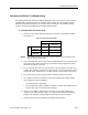
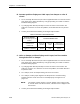
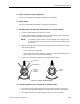
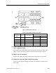
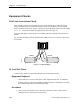
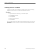
Table Of Contents
- Table of Contents
- How To Use This Manual
- Chapter 1—Hardware
- Chapter 2—Applications for ATEC— Base VAV
- Chapter 3—Applications for ATEC—VAV with Reheat
- Chapter Overview
- Introduction
- Application 2500: VAV Cooling Only
- Application 2501: VAV Cooling or Heating
- Application 2522: VAV with Electric Reheat or Baseboard Radiation
- Application 2523: VAV with Hot Water Reheat (only one reheat valve)
- Application 2524: VAV Series Fan Powered with One Stage of Electric Reheat
- Application 2526: VAV Parallel Fan Powered with One Stage of Electric Reheat
- Application 2473: Slave Mode
- Chapter 4—Point Database
- Chapter 5—Troubleshooting
- Glossary
- Index

Chapter 5—Troubleshooting
5-24 Siemens Building Technologies, Inc.
If the problem still exists after checking the wiring, troubleshoot the externally wired actuator by
interchanging it with a known working actuator. Interchanging actuators can help determine
whether there is a problem with the actuator, the cabling, or the controller. See Table 5-5.
Table 5-5. Actuator Terminal Block Codes.
Electronic Actuator
3-Point Floating Signal, Fail-
in-Place
Terminal Code/Wire Color
damper
(GDE131.1U or
GLB131.1P)
Violet (Y1)
clockwise
Red (G)
COM
Orange (Y2)
counterclockwise
valve
(SSB81U or SSC81U)
Y1
extend
G
COM
Y2
retract
Equipment Required
• Spare, working electronic actuator
• Datamate (Base or Advanced) and IBM-compatible computer, or Handheld PC or Pocket
PC™ with Windows CE, plus communications cable
Procedure
1. Disconnect the existing actuator.
2. Connect a working actuator to the existing cabling in the same manner as the original
actuator.
3. Plug into the communication port on the room temperature sensor.
4. Set the desired point from the list below to 0 and then verify that the actuator strokes fully
closed (or fully opened if it is reverse acting). Next, set the same point to 100, and verify
that the damper or valve strokes fully opened (or closed if it is reverse acting).
• VLV COMD (Point 52) for the hot water valve in Application 2523.
• MTR2 CMD (Point 53) for an externally controlled valve or auxiliary damper (if
present) in slave mode for the ATEC with Reheat.
5. Release the point. Verify that the actuator returns to its normal position.
6. If the spare actuator does not work, then the cable is defective. Repair or replace.
Contact your local Siemens Building Technologies representative.