
Operating Instructions
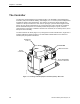
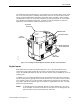
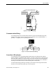
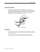
Table Of Contents
- Table of Contents
- How To Use This Manual
- Chapter 1—Hardware
- Chapter 2—Applications for ATEC— Base VAV
- Chapter 3—Applications for ATEC—VAV with Reheat
- Chapter Overview
- Introduction
- Application 2500: VAV Cooling Only
- Application 2501: VAV Cooling or Heating
- Application 2522: VAV with Electric Reheat or Baseboard Radiation
- Application 2523: VAV with Hot Water Reheat (only one reheat valve)
- Application 2524: VAV Series Fan Powered with One Stage of Electric Reheat
- Application 2526: VAV Parallel Fan Powered with One Stage of Electric Reheat
- Application 2473: Slave Mode
- Chapter 4—Point Database
- Chapter 5—Troubleshooting
- Glossary
- Index

Chapter 1—Hardware
1-4 Siemens Building Technologies, Inc.
Analog Inputs
Both models of the controller have Analog Inputs AI 1 and Al 2. Al 1 and Al 2 are used by the
room temperature sensor and the setpoint dial respectively. These Als are not wireable and
are not available for use as auxiliary analog input points.
In addition to AI 1 and AI 2, the ATEC with Reheat includes Al 3 (screw terminals 4 and 5)
and AI 4 (terminals 5 and 6). These inputs can be used for auxiliary temperature inputs to the
controller by connecting 100K Ω thermistors. In Application 2501, AI 3 can be used with a
duct temperature sensor to control whether the ATEC is in cooling or heating mode. See
Chapter 3—Applications for ATEC—VAV with Reheat for more information.
NOTE: In all applications for the ATEC VAV with Reheat, the inputs on the controller
labeled “AI 3” and “AI 4” can each be used either as a DI point or as an AI point,
but neither can be used for both at the same time.
Digital Outputs
Both models of the controller have Digital Outputs DO 1 and DO 2. These outputs are
dedicated to the damper actuator. They are not wireable and are not available for use as
auxiliary output points.
In addition to DO 1 and DO 2, the ATEC with Reheat has DO 3 (screw terminals 1 and 2) and
DO 4 (terminals 2 and 3). DO 3 is used to cycle the first stage of electric heat or baseboard
radiation in Applications 2522, 2524, and 2526. This DO is a spare in Applications 2500 and
2501. In Application 2523, DO 3 and DO 4 control the valve actuator for hot-water reheat.
DO 4 can be used to control an Autozero Module in Applications 2500, 2501, and 2522. In
Application 2522, it can alternatively be used to cycle a second stage of electric reheat. In
Applications 2524 and 2526, DO 4 turns the fan on and off. See Chapter 3—Applications for
ATEC—VAV with Reheat for more information.
The DOs are solid-state contact closures that switch only 24 Vac with a maximum rating of 12
VA. If your applications require a higher voltage or higher VA, then you must use interposing
relays. See Relay Module in this section for more information.
Power Wiring
The controller is powered by 24 Vac. Power wiring connects to the three screw terminals on
the controller labeled "C" (Common) and "H" (Hot), and “E” (Earth) on the terminal block
labeled "24 VAC" (Figure 1-3).