
Operating Instructions
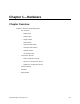
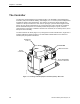
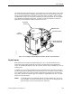
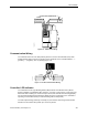
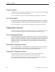
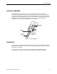
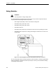
Table Of Contents
- Table of Contents
- How To Use This Manual
- Chapter 1—Hardware
- Chapter 2—Applications for ATEC— Base VAV
- Chapter 3—Applications for ATEC—VAV with Reheat
- Chapter Overview
- Introduction
- Application 2500: VAV Cooling Only
- Application 2501: VAV Cooling or Heating
- Application 2522: VAV with Electric Reheat or Baseboard Radiation
- Application 2523: VAV with Hot Water Reheat (only one reheat valve)
- Application 2524: VAV Series Fan Powered with One Stage of Electric Reheat
- Application 2526: VAV Parallel Fan Powered with One Stage of Electric Reheat
- Application 2473: Slave Mode
- Chapter 4—Point Database
- Chapter 5—Troubleshooting
- Glossary
- Index

The Controller
Siemens Building Technologies, Inc. 1-5
TEC0467R1
C H E
EARTH GND
24 VAC HOT
COMMON
CONTROLLER POWER WIRING
Figure 1-3. ATEC Power Wiring.
Communication Wiring
The controller connects to the field panel by means of a Floor Level Network (FLN) trunk.
Communication wiring connects to the three screw terminals on the controller labeled " + "
(positive), "-" (negative), and "S" (Shield) (Figure 1-4).
TEC0463R1
+
-
S
(SHIELD) (SHIELD)
(+)
(+)
(-)
(-)
Figure 1-4. ATEC Communication Wiring.
Controller LED Indicator
The controller has one Light Emitting Diode (LED) indicator: the BST/FLN LED (“”Basic
Sanity Test/Floor Level Network LED”) (Figure 1-1 on page 1-2 and Figure 1-2 on page 1-3).
When this LED is flashing on and off once per second, the controller is functioning properly
and is communicating with the field panel. When the LED is constantly on, the controller is
operating in stand-alone mode (not communicating with the field panel).
The LED stops flashing (and stays constantly on) two minutes after losing communication
with FLN or two minutes after power up if no FLN is present.