
Operating Instructions
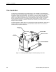
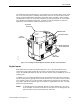
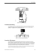
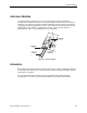
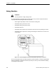
Table Of Contents
- Table of Contents
- How To Use This Manual
- Chapter 1—Hardware
- Chapter 2—Applications for ATEC— Base VAV
- Chapter 3—Applications for ATEC—VAV with Reheat
- Chapter Overview
- Introduction
- Application 2500: VAV Cooling Only
- Application 2501: VAV Cooling or Heating
- Application 2522: VAV with Electric Reheat or Baseboard Radiation
- Application 2523: VAV with Hot Water Reheat (only one reheat valve)
- Application 2524: VAV Series Fan Powered with One Stage of Electric Reheat
- Application 2526: VAV Parallel Fan Powered with One Stage of Electric Reheat
- Application 2473: Slave Mode
- Chapter 4—Point Database
- Chapter 5—Troubleshooting
- Glossary
- Index

Chapter 1—Hardware
1-6 Siemens Building Technologies, Inc.
Damper Actuator
The ATEC includes an actuator that modulates a damper in the supply duct, adjusting airflow
to meet the room’s demand for cooling or heating.
For more information, contact your local Siemens Building Technologies representative.
Air Velocity Sensor
The ATEC includes an air velocity sensor that provides air-velocity inputs to the controller.
The sensor is located in the supply duct, and pneumatic tubing connects it to the controller at
the connections labeled “Hi” and “Lo” (Figure 1-1 on page 1-2 and Figure 1-2 on page 1-3).
For more information, contact your local Siemens Building Technologies representative.
Temperature Sensors
Temperature sensors used with the ATEC include an electronic room temperature sensor (or
a return-duct temperature sensor) and an optional supply-duct temperature sensor.
Room Temperature Sensor
The Terminal Equipment Controller room temperature sensor connects to the controller by
means of a cable terminated at both ends with a six conductor RJ-11 plug-in connector. See
Figure 1-1 on page 1-2 and Figure 1-2 on page 1-3 for the location of the room temperature
sensor/man machine interface (MMI) port. The room temperature sensor can include a
setpoint dial and/or an override switch that temporarily switches the controller from night
mode to day mode.
Return-Duct Temperature Sensor
If the room does not offer a suitable location for a room temperature sensor, the ATEC can
use a Terminal Equipment Controller temperature sensor located in the return duct. This
sensor uses the same RJ-11 connector as the room temperature sensor.
Supply-Duct Temperature Sensor
For Application 2501, an optional duct temperature sensor provides supply-duct air
temperature sensing inputs to the controller. This sensor is wired to AI 3.
For more information about temperature sensors from Siemens Building Technologies, Inc.,
contact your local Siemens Building Technologies representative.