
Operating Instructions
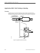
Table Of Contents
- Table of Contents
- How To Use This Manual
- Chapter 1—Hardware
- Chapter 2—Applications for ATEC— Base VAV
- Chapter 3—Applications for ATEC—VAV with Reheat
- Chapter Overview
- Introduction
- Application 2500: VAV Cooling Only
- Application 2501: VAV Cooling or Heating
- Application 2522: VAV with Electric Reheat or Baseboard Radiation
- Application 2523: VAV with Hot Water Reheat (only one reheat valve)
- Application 2524: VAV Series Fan Powered with One Stage of Electric Reheat
- Application 2526: VAV Parallel Fan Powered with One Stage of Electric Reheat
- Application 2473: Slave Mode
- Chapter 4—Point Database
- Chapter 5—Troubleshooting
- Glossary
- Index

Application 2521: VAV Cooling or Heating
Siemens Building Technologies, Inc. 2-15
Night Mode Override Switch
If an override switch is present on the room temperature sensor and a value (in hours) other
than zero has been entered into OVRD TIME (Point 20), pressing the override switch resets
the controller to day operational mode for the time period that is set in OVRD TIME. The
status of NGT OVRD (Point 21) changes to DAY. After the override time elapses, the
controller returns to night mode and NGT OVRD changes back to NIGHT.
It is only when the controller is in night mode that the override switch on the room sensor has
any effect on the controller.
Heating/Cooling Switchover
In order for the controller to function properly, use one of the following two options for the
heating/cooling switchover for this application.
1. If the controller is connected to a field panel, the field panel can command
SUPPLY TEMP (Point 40).
When SUPPLY TEMP is commanded below the value of COOL TEMP (Point 61), the
controller sets HEAT.COOL (Point 5) to COOL, switching the controller to cooling mode.
When SUPPLY TEMP is commanded above the value of HEAT TEMP (Point 62), the
controller sets HEAT.COOL to HEAT, switching the controller to heating mode.
2. If the controller is connected to a field panel, the field panel can switch the controller
between heating and cooling modes by commanding HEAT.COOL to HEAT or COOL.
Control Loops
The terminal box is controlled by three Proportional, Integral, and Derivative (PID) control
loops: two temperature loops and a flow loop.
The two temperature loops are a cooling loop and a heating loop. The active temperature
loop maintains room temperature at the value in CTL STPT (Point 92). See Control
Temperature Setpoints (page 2-14).
Cooling Loop—The cooling loop uses the values of CTL STPT and CTL TEMP (Point 78) to
generate the cooling loopout, which is then used to generate FLOW STPT (Point 93). FLOW
STPT is calculated between CLG FLOW MIN (Point 31) and CLG FLOW MAX (Point 32).
Heating Loop—The heating loop uses the values of CTL STPT and CTL TEMP to generate
the heating loopout, which is then used to generate the FLOW STPT. FLOW STPT is
calculated between HTG FLOW MIN (Point 33) and HTG FLOW MAX (Point 34).
Flow Loop—The flow loop maintains airflow between CTL FLOW MIN (Point 76) and CTL
FLOW MAX (Point 77) by modulating DMPR COMD (Point 48).