
Operating Instructions
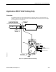
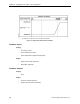
Table Of Contents
- Table of Contents
- How To Use This Manual
- Chapter 1—Hardware
- Chapter 2—Applications for ATEC— Base VAV
- Chapter 3—Applications for ATEC—VAV with Reheat
- Chapter Overview
- Introduction
- Application 2500: VAV Cooling Only
- Application 2501: VAV Cooling or Heating
- Application 2522: VAV with Electric Reheat or Baseboard Radiation
- Application 2523: VAV with Hot Water Reheat (only one reheat valve)
- Application 2524: VAV Series Fan Powered with One Stage of Electric Reheat
- Application 2526: VAV Parallel Fan Powered with One Stage of Electric Reheat
- Application 2473: Slave Mode
- Chapter 4—Point Database
- Chapter 5—Troubleshooting
- Glossary
- Index

Chapter 3—Applications for ATEC—VAV with Reheat
3-2 Siemens Building Technologies, Inc.
Introduction
Basic Operation
The Actuating Terminal Equipment Controller—Electronic Output (ATEC) provides Direct
Digital Control (DDC) for Variable Air Volume (VAV) terminal box applications. Temperature
control varies with the application. If present, heating can be provided by hot water, up to two
stages of electric reheat, or optional baseboard radiation. Application 2501 requires the
central air-handling unit to provide warm air during the heating mode. For cooling, the
controller modulates the supply-air damper of the terminal box.
Control Operation
The ATEC can operate with centralized control or stand-alone control.
Centralized Control—A controller operating under centralized control means that it is
connected, by means of a Floor Level Network (FLN), with an APOGEE field panel.
Stand-alone Control—A controller operating under stand-alone control means that it is
providing independent DDC control to a space.
Illustrations
Each application in this section contains three types of illustrations: control drawings, control
schedules, and wiring diagrams.
Control Drawing—A schematic representation of an ATEC. It shows the associated control
components and wiring.
Control Schedule—A graphical representation of the terminal box operation as controlled by
a specific ATEC application. Each control drawing has one or two control schedules
associated with it.
Wiring Diagram—Each wiring diagram shows the terminations that correspond to a specific
ATEC application.
Controller Points
In this manual, controller "points" appear in uppercase letters, the same as if viewed with the
Datamate Software tool. For example, DAY.NGT (Point 29). DAY.NGT is the point that
indicates the day or night operational mode of the controller.
Chapter 4—Point Database lists and defines all points used by this controller. You may want
to refer to this chapter while reading the Sequence of Operation material that describes the
various ATEC applications.