
Operating Instructions
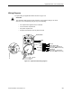
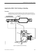
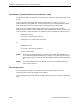
Table Of Contents
- Table of Contents
- How To Use This Manual
- Chapter 1—Hardware
- Chapter 2—Applications for ATEC— Base VAV
- Chapter 3—Applications for ATEC—VAV with Reheat
- Chapter Overview
- Introduction
- Application 2500: VAV Cooling Only
- Application 2501: VAV Cooling or Heating
- Application 2522: VAV with Electric Reheat or Baseboard Radiation
- Application 2523: VAV with Hot Water Reheat (only one reheat valve)
- Application 2524: VAV Series Fan Powered with One Stage of Electric Reheat
- Application 2526: VAV Parallel Fan Powered with One Stage of Electric Reheat
- Application 2473: Slave Mode
- Chapter 4—Point Database
- Chapter 5—Troubleshooting
- Glossary
- Index

Application 2500: VAV Cooling Only
Siemens Building Technologies, Inc. 3-9
Wiring Diagram
The point wiring for Application 2500 is shown in Figure 3-3.
CAUTION:
The controller’s DOs control 24 Vac loads only. The maximum rating is 12 VA for
each DO. Use an interposing relay for any of the following:
• VA requirements higher than the maximum
• 110 or 220 Vac requirements
• DC power requirements
• Separate transformers used to power the load
Lo
Hi
654321
Spare DO
Autozero Module (Opt.)
Spare AI (100K Thermistor) or
Spare DI (Dry contact closure only)
Wall Switch or
Spare AI (100K Thermistor) or
Spare DI (Dry contact closure only)
24 Vac
FLN
90
90
4
5
TEC2500WDR2
RTS
DO3
C
DO4
AI3
C
AI4
BST/FLN LED
Figure 3-3. Application 2500 Wiring Diagram.