
Operating Instructions
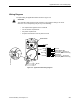
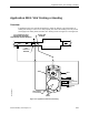
Table Of Contents
- Table of Contents
- How To Use This Manual
- Chapter 1—Hardware
- Chapter 2—Applications for ATEC— Base VAV
- Chapter 3—Applications for ATEC—VAV with Reheat
- Chapter Overview
- Introduction
- Application 2500: VAV Cooling Only
- Application 2501: VAV Cooling or Heating
- Application 2522: VAV with Electric Reheat or Baseboard Radiation
- Application 2523: VAV with Hot Water Reheat (only one reheat valve)
- Application 2524: VAV Series Fan Powered with One Stage of Electric Reheat
- Application 2526: VAV Parallel Fan Powered with One Stage of Electric Reheat
- Application 2473: Slave Mode
- Chapter 4—Point Database
- Chapter 5—Troubleshooting
- Glossary
- Index

Chapter 3—Applications for ATEC—VAV with Reheat
3-16 Siemens Building Technologies, Inc.
Day and Night Modes
The day/night status of the space is determined by the status of DAY.NGT (Point 29). The
control of this point differs depending on whether the controller is monitoring the status of a
wall switch or is connected to a field panel.
When a wall switch is physically connected to the controller at the AI/DI port labeled “AI 4”
(Figure 3-4 on page 3-13 and Figure 3-6 on page 3-20), and WALL SWITCH (Point 18) is set
to YES, the controller monitors the status of DI 4 (Point 24). When DI 4 is ON (the switch is
closed), DAY.NGT is set to DAY indicating that the controller is in day mode. When DI 4 is
OFF (the switch is open), DAY.NGT is set to NIGHT indicating that the controller is in night
mode.
When WALL SWITCH is set to NO, the controller does not monitor the status of the wall
switch, even if one is connected to it. If the controller is operating stand-alone, it stays in day
mode all the time. If the controller is operating with centralized control (that is, connected to a
field panel), the field panel can send an operator or PPCL command to override the status of
DAY.NGT. See the Powers Process Control Language (PPCL) User’s Manual (125-1896)
and Field Panel User’s Manual (125-1895) for more information.
Night Mode Override Switch
If an override switch is present on the room temperature sensor and a value (in hours) other
than zero has been entered into OVRD TIME (Point 20), pressing the override switch resets
the controller to day operational mode for the time period that is set in OVRD TIME. The
status of NGT OVRD (Point 21) changes to DAY. After the override time elapses, the
controller returns to night mode and NGT OVRD changes back to NIGHT.
It is only when the controller is in night mode that the override switch on the room sensor has
any effect on the controller.
Heating/Cooling Switchover
There are three options for the heating/cooling switchover for this application. In order for the
controller to function properly, one of the following three options must be used:
1. A temperature sensor is installed in the supply air ductwork. The controller uses the
measured temperature point, SUPPLY TEMP (Point 15), to determine whether it is in
heating or cooling mode.
When the value of SUPPLY TEMP is less than the value of COOL TEMP (Point 61), the
controller sets HEAT.COOL (Point 5) to COOL, switching the controller to cooling mode.
When the value of SUPPLY TEMP is greater than the value of HEAT TEMP (Point 62),
the controller sets HEAT.COOL to HEAT, switching the controller to heating mode.