
Operating Instructions
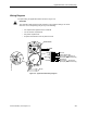
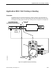
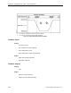
Table Of Contents
- Table of Contents
- How To Use This Manual
- Chapter 1—Hardware
- Chapter 2—Applications for ATEC— Base VAV
- Chapter 3—Applications for ATEC—VAV with Reheat
- Chapter Overview
- Introduction
- Application 2500: VAV Cooling Only
- Application 2501: VAV Cooling or Heating
- Application 2522: VAV with Electric Reheat or Baseboard Radiation
- Application 2523: VAV with Hot Water Reheat (only one reheat valve)
- Application 2524: VAV Series Fan Powered with One Stage of Electric Reheat
- Application 2526: VAV Parallel Fan Powered with One Stage of Electric Reheat
- Application 2473: Slave Mode
- Chapter 4—Point Database
- Chapter 5—Troubleshooting
- Glossary
- Index

Application 2501: VAV Cooling or Heating
Siemens Building Technologies, Inc. 3-17
2. If the controller is connected to a field panel, the field panel can command
SUPPLY TEMP.
When SUPPLY TEMP is commanded below the value of COOL TEMP, the controller
sets HEAT.COOL to COOL, switching the controller to cooling mode.
When SUPPLY TEMP is commanded above the value of HEAT TEMP, the controller sets
HEAT.COOL to HEAT, switching the controller to heating mode.
3. If the controller is connected to a field panel, the field panel can switch the controller
between heating and cooling modes by commanding HEAT.COOL to HEAT or COOL.
Control Loops
The terminal box is controlled by three Proportional, Integral, and Derivative (PID) control
loops: two temperature loops and a flow loop.
The two temperature loops are a cooling loop and a heating loop. The active temperature
loop maintains room temperature at the value in CTL STPT (Point 92). See Control
Temperature Setpoints (page 3-15).
Cooling Loop—The cooling loop uses the values of CTL STPT and CTL TEMP (Point 78) to
generate the cooling loopout, which is then used to generate FLOW STPT (Point 93). FLOW
STPT is calculated between CLG FLOW MIN (Point 31) and CLG FLOW MAX (Point 32).
Heating Loop—The heating loop uses the values of CTL STPT and CTL TEMP to generate
the heating loopout, which is then used to generate the FLOW STPT. FLOW STPT is
calculated between HTG FLOW MIN (Point 33) and HTG FLOW MAX (Point 34).
Flow Loop—The flow loop maintains airflow between CTL FLOW MIN (Point 76) and CTL
FLOW MAX (Point 77) by modulating DMPR COMD (Point 48).
Calibration of Air Velocity Sensor
Calibration of the controller’s internal air velocity sensor is periodically required to maintain
accurate air velocity readings. CAL SETUP (Point 95) is set with the desired calibration
option during controller startup. Depending on the value of CAL SETUP, calibration may be
set to take place automatically or manually. When CAL AIR (Point 94) has a setting of YES,
calibration is in progress.
• For a controller used without an Autozero Module (CAL MODULE, Point 87, is set to
NO), the damper is commanded closed to get a zero airflow reading during
calibration.
• For a controller used with an Autozero Module (CAL MODULE is set to YES),
calibration occurs without closing the damper.
At the end of a calibration sequence, CAL AIR automatically returns to NO. A setting of NO
indicates that the controller is not in a calibration sequence.