
Operating Instructions
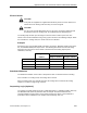
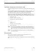
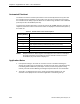
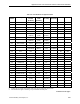
Table Of Contents
- Table of Contents
- How To Use This Manual
- Chapter 1—Hardware
- Chapter 2—Applications for ATEC— Base VAV
- Chapter 3—Applications for ATEC—VAV with Reheat
- Chapter Overview
- Introduction
- Application 2500: VAV Cooling Only
- Application 2501: VAV Cooling or Heating
- Application 2522: VAV with Electric Reheat or Baseboard Radiation
- Application 2523: VAV with Hot Water Reheat (only one reheat valve)
- Application 2524: VAV Series Fan Powered with One Stage of Electric Reheat
- Application 2526: VAV Parallel Fan Powered with One Stage of Electric Reheat
- Application 2473: Slave Mode
- Chapter 4—Point Database
- Chapter 5—Troubleshooting
- Glossary
- Index

Chapter 3—Applications for ATEC—VAV with Reheat
3-32 Siemens Building Technologies, Inc.
The damper moves from minimum position to fully open as HTG LOOPOUT increases from
FLOW START to FLOW END. If FLOW START and FLOW END are both set to 0% (default
value), the damper stays at minimum position while in heating mode.
The cycle for the reheat ranges from always off to always on as HTG LOOPOUT increases
from REHEAT START to REHEAT END. Default values for these points are 0% and 100%
respectively. See Electric Reheat (page 3-31) for more information.
By varying the values of these start and end points, the damper and the reheat can be
sequenced in series, parallel, or overlapping, as shown in the following table:
Series Parallel Overlapping Minimum Flow
(Default Value)
FLOW START 0% 0% 0% 0%
FLOW END 50% 100% 75% 0%
REHEAT START 50% 0% 25% 0%
REHEAT END 100% 100% 100% 100%
Electric Heat Interlock
The electric heat stages are enabled as long as FLOW (Point 75) is greater than EHEAT
FLOW (Point 60). The electric heat stages are not disabled (turned off) until FLOW is less
than EHEAT FLOW minus 5%. Once disabled, FLOW must become greater than EHEAT
FLOW before the electric heat stages return to normal control.
CAUTION:
Do not set EHEAT FLOW to less than 5%, otherwise the electric heat
interlock will be disabled.
Calibration of Air Velocity Sensor
Calibration of the controller’s internal air velocity sensor is periodically required to maintain
accurate air velocity readings. CAL SETUP (Point 95) is set with the desired calibration
option during controller startup. Depending on the value of CAL SETUP, calibration may be
set to take place automatically or manually. When CAL AIR (Point 94) has a setting of YES,
calibration is in progress.
• For a controller used without an Autozero Module (CAL MODULE, Point 87, is set to
NO), the damper is commanded closed to get a zero airflow reading during
calibration.
• For a controller used with an Autozero Module (CAL MODULE is set to YES),
calibration occurs without closing the damper.
At the end of a calibration sequence, CAL AIR automatically returns to NO. A setting of NO
indicates that the controller is not in a calibration sequence.