
Operating Instructions
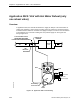
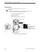
Table Of Contents
- Table of Contents
- How To Use This Manual
- Chapter 1—Hardware
- Chapter 2—Applications for ATEC— Base VAV
- Chapter 3—Applications for ATEC—VAV with Reheat
- Chapter Overview
- Introduction
- Application 2500: VAV Cooling Only
- Application 2501: VAV Cooling or Heating
- Application 2522: VAV with Electric Reheat or Baseboard Radiation
- Application 2523: VAV with Hot Water Reheat (only one reheat valve)
- Application 2524: VAV Series Fan Powered with One Stage of Electric Reheat
- Application 2526: VAV Parallel Fan Powered with One Stage of Electric Reheat
- Application 2473: Slave Mode
- Chapter 4—Point Database
- Chapter 5—Troubleshooting
- Glossary
- Index

Application 2523: VAV with Hot Water Reheat (only one reheat valve)
Siemens Building Technologies, Inc. 3-45
Control Loops
The terminal box is controlled by three Proportional, Integral, and Derivative (PID) control
loops: two temperature loops and a flow loop.
The two temperature loops are a cooling loop and a heating loop. The active temperature
loop maintains room temperature at the value in CTL STPT (Point 92). See Control
Temperature Setpoints (page 3-43).
Cooling Loop—The cooling loop uses the values of CTL STPT and CTL TEMP (Point 78) to
generate the cooling loopout, which is then used to generate FLOW STPT (Point 93). FLOW
STPT is calculated between CLG FLOW MIN (Point 31) and CLG FLOW MAX (Point 32).
Heating Loop—If the controller is in heating mode, the operation of the flow loop is flexible.
As described in Sequencing Logic (page 3-46), it can be set up to do one of the following:
• Constantly maintain an airflow out of the terminal box equal to HTG FLOW MIN
(Point 33).
• Operate in sequence with the electric reheat.
• Operate parallel with the electric reheat.
• Have its operation overlap with the operation of the electric reheat.
If the first option described above is chosen, HTG LOOPOUT (Point 80) controls the electric
reheat in order to maintain the room temperature. If any one of the last three options is
chosen, HTG LOOPOUT controls both the flow loop setpoint (FLOW STPT) and the electric
reheat in order to maintain the room temperature. See Sequencing Logic for more
information.
HTG LOOPOUT adjusts the value of FLOW STPT differently depending on which flow loop
setup is chosen. However, in all cases FLOW STPT is between HTG FLOW MIN (Point 33)
and HTG FLOW MAX (Point 34).
Flow Loop—The flow loop maintains the airflow between CTL FLOW MIN (Point 76) and
CTL FLOW MAX (Point 77) by modulating DMPR COMD (Point 48).
Hot Water Reheat
CAUTION:
Do not set HTG FLOW MIN (Point 33) to 0 cfm (0 lps). A minimum airflow should
be provided across the heating coils, for ventilation and for dispersing heat.
When the controller is in heating mode, HTG LOOPOUT controls the value of VLV COMD
(Point 52). As HTG LOOPOUT traverses the range between REHEAT START and REHEAT
END, the value of VLV COMD ranges from 0 to 100% open.
When the controller is in cooling mode, the heating valve is closed.